
Article
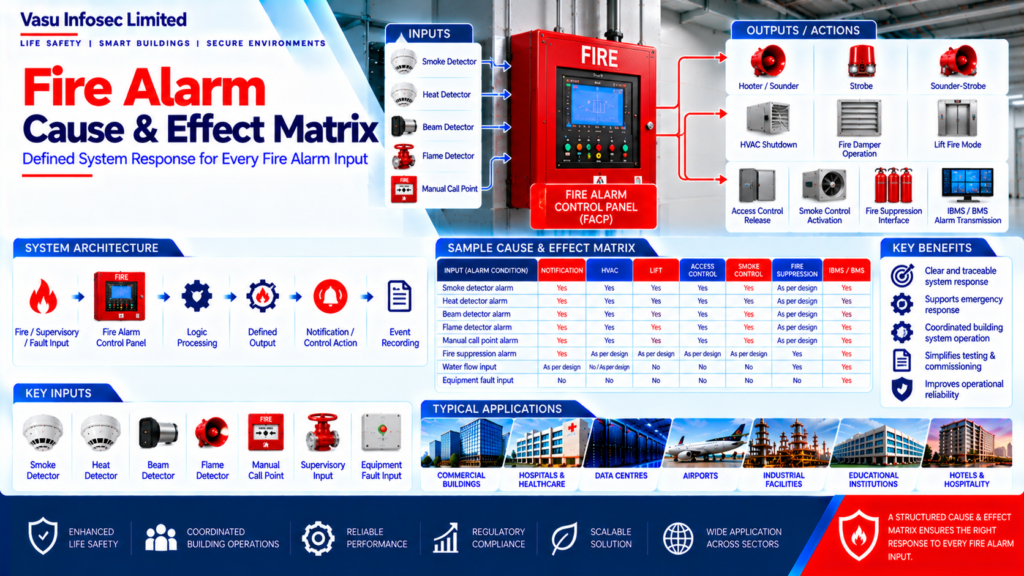
Fire Alarm Cause & Effect Matrix
Oct 2026
Direct Answer
A Fire Alarm Cause & Effect Matrix documents how approved system inputs—such as detector alarms, manual call point alarms, faults or supervisory signals—are intended to trigger defined outputs or actions. It is used as a coordinated reference for design, programming, testing, commissioning and handover.
1. Engineering Overview
A Fire Alarm Cause & Effect Matrix defines the programmed relationship between system inputs and the corresponding outputs or actions. It provides a structured basis for configuring, testing and validating how the Fire Alarm System responds to alarms, faults, supervisory conditions and approved external inputs.
2. Basic Cause & Effect Architecture
Fire / Supervisory / Fault Input → Fire Alarm Control Panel → Logic Processing → Defined Output → Notification / Control / Interface Action → Event Recording
3. Purpose of the Matrix
The Cause & Effect Matrix establishes a clear and traceable response philosophy. It helps ensure that every approved initiating condition produces the intended system response and provides a common reference for design, programming, testing, commissioning and handover.
4. Input Categories
Typical inputs may include:
- Smoke detector alarm
- Heat detector alarm
- Beam detector alarm
- Flame detector alarm
- Manual call point alarm
- Fire suppression alarm / supervisory input
- Water flow input, where applicable
- Valve supervisory input, where applicable
- Equipment fault input
- System supervisory input
5. Output Categories
Typical outputs may include:
- Hooter / sounder activation
- Strobe activation
- Sounder-strobe activation
- HVAC shutdown
- Fire damper operation
- Lift fire mode
- Access control release
- Smoke control activation
- Fire suppression interface
- IBMS / BMS alarm transmission
- Remote monitoring output
6. Alarm Cause & Effect Sequence
Initiating Condition → Alarm Recognition → Panel Processing → Defined Cause & Effect Logic → Notification Activation → External Control Actions → Event Recording → Emergency Response
7. Zone-Based Cause & Effect
Where the approved design requires zone-based logic, an alarm from a defined zone may initiate specific notification and control actions. The matrix should clearly identify which zones operate which outputs and under what conditions.
8. Device-Based Cause & Effect
In addressable systems, individual devices may be programmed to initiate specific outputs or sequences where required. Device-based logic should be clearly documented and coordinated with the approved fire strategy.
9. Notification Logic
The matrix should define the notification response for each relevant alarm input.
Examples include:
- Alarm input → general sounder activation
- Alarm input → local notification
- Alarm input → sounder and strobe activation
- Alarm input → programmed evacuation sequence
10. HVAC & Fire Damper Interface
Where specified, fire alarm inputs may initiate HVAC-related actions such as equipment shutdown or fire damper operation. The exact interface sequence should be established from the approved mechanical and fire alarm coordination requirements.
11. Lift Interface
A fire alarm condition may initiate the approved lift fire mode or recall sequence. The Cause & Effect Matrix should identify the initiating condition, affected lift group and required output interface.
12. Access Control Interface
Where required, a fire alarm condition may release selected access-controlled doors or activate another approved emergency access function. The matrix should clearly identify the affected doors, areas or access-control groups.
13. Fire Suppression Interface
The Fire Alarm System may monitor or control approved interfaces with fire suppression systems. The matrix should distinguish alarm, supervisory and fault signals and clearly define the corresponding actions.
14. IBMS / BMS Interface
The Cause & Effect Matrix may define transmission of fire alarm, fault and supervisory information to IBMS / BMS or other monitoring platforms. Signal naming and interface status should remain consistent across the system documentation.
15. Fault & Supervisory Logic
Fault and supervisory inputs should be treated according to their intended function and should not be automatically treated as fire alarms unless specifically required by the approved design. The matrix should clearly identify the response to each condition.
16. Testing & Commissioning
Cause & Effect testing should verify every approved input-output relationship.
Testing may include:
- Detector alarm activation
- Manual call point activation
- Zone alarm testing
- Notification activation
- HVAC interface testing
- Lift interface testing
- Access control interface testing
- Suppression interface testing
- IBMS / BMS signal verification
- Fault and supervisory testing
- Reset and restoration
17. Matrix Development Considerations
The matrix should be developed using:
- Approved fire strategy
- Fire alarm zoning philosophy
- Detection layout
- Equipment schedules
- Mechanical coordination
- Electrical coordination
- Lift requirements
- Access control requirements
- Fire suppression requirements
- IBMS / BMS requirements
- Authority requirements
18. Documentation & Revision Control
The Cause & Effect Matrix should be controlled as an engineering document. Changes to inputs, outputs or sequences should be reflected in the latest approved revision and coordinated with panel programming, drawings and testing documentation.
19. Common Engineering Considerations
Engineering review should verify:
- Every relevant input is represented
- Every required output is represented
- Logic is unambiguous
- Zone / device references are correct
- Interface responsibilities are clear
- Alarm, fault and supervisory conditions are differentiated
- Testing can demonstrate each relationship
- Final programming matches the approved matrix
20. Engineering Objective
The engineering objective is:
Defined Inputs → Clear Logic → Correct Outputs → Coordinated Interfaces → Controlled Emergency Response → Complete Testing → Accurate Documentation → Reliable Fire Alarm Cause & Effect Performance
Frequently Asked Questions
What is a fire alarm Cause & Effect Matrix?
It is a structured record of the relationship between initiating inputs and the outputs or actions programmed in the fire alarm system.
What information should the matrix contain?
It should identify relevant inputs, defined outputs, zone/device references, the required logic, interface actions and any applicable alarm, fault or supervisory distinctions.
Are faults and supervisory signals treated as fire alarms?
Not automatically. The source document states that fault and supervisory inputs should be treated according to their intended function and should not be treated as fire alarms unless specifically required by the approved design.
Does every fire alarm activate HVAC, lifts or access control?
No universal response is implied. Such actions should be included only where required by the approved fire strategy and coordinated project requirements.
How should the matrix be tested?
Testing should verify each approved input-output relationship, including relevant notifications and interfaces, fault/supervisory behaviour, event recording, reset and restoration.
Why is revision control important?
Changes to inputs, outputs or sequences must be reflected in the latest approved matrix and coordinated with panel programming, drawings and testing records.
SEO and CMS Recommendations
| SEO title | Fire Alarm Cause & Effect Matrix: Design and Testing | Vasu Infosec |
| Meta description | Learn how a fire alarm Cause & Effect Matrix maps alarm, fault and supervisory inputs to approved notification, control and interface actions. |
| Suggested URL slug | /fire-alarm-cause-and-effect-matrix/ |
| Primary keyword | fire alarm cause and effect matrix |
| Related keywords | fire alarm input output matrix, fire alarm interface logic, fire alarm commissioning test, fire alarm control sequence |
| Suggested internal links | Fire Alarm Zoning Philosophy; Fire Alarm Loop Architecture; Hooter, Sounder & Strobe Comparison; Manual Call Point: Components & Operation |
Technical Review and Pre-Publication Checklist
- Confirm every input and output against the approved fire strategy, equipment schedules and interface documents.
- Check that zone/device references, signal names and programmed logic match approved drawings and panel configuration.
- Verify HVAC, damper, lift, access-control, suppression and IBMS/BMS interfaces with the responsible disciplines and approved requirements.
- Keep fire alarm, fault and supervisory conditions clearly differentiated unless an approved design specifically defines otherwise.
- Confirm each approved input-output relationship can be demonstrated and recorded during commissioning.
- Maintain revision control and coordinate updates with panel programming, drawings, test records and as-built documents.
- Confirm applicable authority requirements and project standards; the source does not name a specific standard or edition.
- Keep Vasu Infosec Limited’s obligations within the approved contractual scope and authorised project documents.