
Article
Fire Alarm Loop Architecture
Oct 2026
Direct Answer
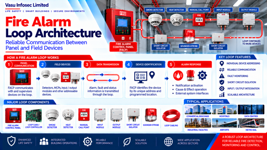
Fire alarm loop architecture defines how addressable field devices communicate with and are supervised by the Fire Alarm Control Panel (FACP). A properly engineered loop supports device identification, alarm transmission, fault monitoring and isolation, subject to the selected manufacturer’s approved architecture and the project’s approved design.
1. Engineering Overview
The Fire Alarm Loop Architecture defines the communication and connection arrangement between addressable field devices and the Fire Alarm Control Panel. A properly engineered loop provides reliable device communication, alarm transmission, fault monitoring, isolation and system supervision while supporting the approved detection and control philosophy.
2. Basic Loop Architecture
Fire Alarm Control Panel → Loop Interface / Loop Card → Addressable Devices → Input / Output Modules → Short Circuit Isolators → Return Path / Loop Completion → Fire Alarm Control Panel
3. Loop Operating Principle
An addressable fire alarm loop provides communication between the control panel and connected field devices. The panel continuously communicates with and supervises devices connected to the loop. Device information, alarm conditions, fault conditions and control commands are transmitted through the approved loop architecture.
4. Major Loop Components
A typical addressable loop may include:
- Fire Alarm Control Panel
- Loop controller / loop card
- Smoke detectors
- Heat detectors
- Manual call points
- Input modules
- Output / control modules
- Monitor modules
- Short circuit isolators
- Addressable notification devices, where supported
- Loop cabling and termination arrangements
5. Loop Topology
The loop topology should follow the selected manufacturer’s approved architecture. Depending on the system, the loop may support communication to multiple addressable devices while providing a monitored return path to the control panel.
6. Device Addressing
Each addressable field device should have a unique address within the loop. The address should correspond with the approved device schedule, drawing, programmed location and Cause & Effect Matrix to maintain accurate identification.
7. Short Circuit Isolation
Short circuit isolators may be incorporated into the loop to limit the effect of a short circuit on connected field devices. Their arrangement should follow the approved system architecture and manufacturer requirements.
8. Loop Capacity
Loop capacity should be verified during engineering design. The assessment should consider number of addressable devices, device types, input / output modules, notification loads where applicable, loop current, cable length, voltage drop, manufacturer limits and future expansion requirements.
9. Loop Cable Selection
Loop cabling should be selected in accordance with the approved fire alarm design and equipment requirements. Engineering considerations include cable type, conductor size, voltage drop, current carrying capacity, fire resistance requirements, electromagnetic compatibility, route segregation and mechanical protection.
10. Device Communication
The loop should provide reliable communication between the panel and connected devices. Communication performance should be maintained under normal operating conditions and appropriate fault conditions as defined by the selected system.
11. Alarm Transmission
When an addressable detector or manual call point operates, the device communicates the alarm condition to the Fire Alarm Control Panel. The panel identifies the device according to its programmed address and executes the approved alarm response.
12. Fault Monitoring
The loop should be supervised for abnormal conditions as supported by the selected system. Potential faults include open circuit, short circuit, device communication failure, device removal, earth fault where applicable and loop controller fault.
13. Input & Output Modules
Addressable input modules allow external devices or signals to be monitored by the fire alarm system. Output / control modules allow the panel to control external equipment according to the approved Cause & Effect Matrix.
14. Loop Zoning & Logical Grouping
Physical loop architecture and logical fire alarm zoning are separate but coordinated design considerations. Devices may be grouped into logical zones while remaining individually identifiable on the addressable loop.
15. Cause & Effect Integration
Loop-connected input and output devices may participate in programmed Cause & Effect functions. Examples include detector alarm to sounder activation, MCP operation to alarm notification, fire alarm to HVAC shutdown, lift fire mode, access control release and fire suppression interface.
16. Testing & Commissioning
Loop testing should verify the complete communication path and connected devices. Testing may include continuity verification, device addressing, device communication, alarm activation, fault simulation, isolator operation, input / output operation, Cause & Effect testing and panel event identification.
17. Inspection & Maintenance
Loop systems should be periodically inspected and tested according to the approved maintenance programme and manufacturer requirements. Activities may include device status review, fault history review, loop communication check, isolator inspection, cable / termination inspection, device testing and address verification.
18. Common Engineering Considerations
Engineering review should verify:
- Correct loop architecture
- Manufacturer compatibility
- Loop capacity
- Device addressing
- Cable selection
- Voltage drop
- Short circuit isolation
- Fault monitoring
- Cause & Effect programming
- Future expansion
19. Documentation
Loop documentation should include, as applicable:
- Loop architecture diagram
- Loop drawings
- Device schedule
- Address list
- Cable schedule
- Loop loading / capacity calculation
- Input / Output schedule
- Cause & Effect Matrix
- Testing records
- Commissioning records
- As-built documentation
20. Engineering Objective
The engineering objective is:
Robust Loop Architecture → Correct Device Addressing → Reliable Communication → Effective Fault Isolation → Accurate Alarm Identification → Controlled Outputs → Verified Testing → Maintainable Loop Network → Reliable Fire Alarm System Performance
Frequently Asked Questions
What is a fire alarm loop?
It is the communication and connection arrangement between the Fire Alarm Control Panel and connected addressable field devices.
Why is device addressing important?
A unique device address linked to the approved schedule, drawings and programmed location helps the panel identify the correct device or alarm condition.
What determines loop capacity?
The source identifies device count and types, modules, applicable notification loads, loop current, cable length, voltage drop, manufacturer limits and future expansion requirements.
What faults may be monitored?
Depending on the selected system, these may include open circuit, short circuit, device communication failure, device removal, earth fault where applicable and loop controller fault.
Does physical loop architecture equal fire alarm zoning?
No. The source distinguishes physical loop architecture from logical zoning; devices may be grouped into logical zones while remaining individually identifiable on the addressable loop.
What should loop commissioning verify?
As applicable, continuity, addressing, device communication, alarm activation, fault simulation, isolator operation, input/output operation, Cause & Effect functions and panel event identification.
SEO & CMS Metadata Suggestions
| SEO title | Fire Alarm Loop Architecture: Components, Capacity & Testing | Vasu Infosec |
| Meta description | Learn how addressable fire alarm loops connect field devices to the control panel, including device addressing, loop capacity, fault monitoring, cable selection and commissioning. |
| Suggested URL slug | /fire-alarm-loop-architecture/ |
| Primary keyword | fire alarm loop architecture |
| Related keywords | addressable fire alarm loop, fire alarm loop capacity, short circuit isolator, fire alarm device addressing, fire alarm loop testing |
Suggested Internal Links
- Fire Alarm Control Panel: Architecture & Functions
- Addressable vs Conventional Fire Alarm Systems
- Fire Detection to Alarm Sequence
- Manual Call Point: Components & Operation
Pre-Publication Technical Review
- Confirm the selected manufacturer’s approved loop topology, device limits and compatibility.
- Verify loop capacity, cable type/size, cable length, voltage drop and current calculations against approved design documents.
- Confirm isolator placement, fault monitoring and notification loads where applicable.
- Verify the approved Cause & Effect Matrix and commissioning procedures.
- Confirm applicable standards, editions and authority requirements from the project design basis; do not infer compliance from this article alone.
- Ensure project-specific responsibilities and deliverables remain within Vasu Infosec Limited’s approved contractual scope.