
Article
Fire Alarm System: Complete Architecture
Oct 2026
Direct Answer
A Fire Alarm System detects fire-related conditions, identifies the affected location, processes alarm signals, alerts occupants and initiates approved control functions and interfaces. Its architecture typically includes detection devices, a Fire Alarm Control Panel (FACP), notification appliances, power supplies, field circuits and interfaces with other building systems. The final design must be based on the approved project requirements, applicable standards, manufacturer instructions and Authority Having Jurisdiction (AHJ) requirements.
1. Engineering Overview
A Fire Alarm System is an integrated life-safety system designed to detect fire-related conditions, process alarm information, provide audible and visual notification, initiate programmed control functions and communicate with associated building systems. The architecture should address detection, control, notification, interfaces, power supply, monitoring, testing, commissioning and maintenance as a coordinated system.
2. Complete System Architecture
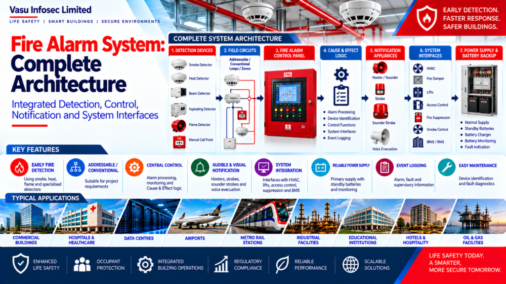
Detection Devices → Addressable / Conventional Field Circuits → Fire Alarm Control Panel → Cause & Effect Logic → Notification Appliances → Approved System Interfaces → Monitoring / BMS Interfaces → Power Supply and Standby Battery
This is a high-level representation. Actual system topology, circuit classification, interface arrangements and power architecture depend on the approved design and selected equipment.
3. System Design Inputs
Develop the architecture from verified project information, including:
- Building and facility layout
- Occupancy classification and fire risk assessment
- Fire zoning and detection philosophy
- Alarm notification and evacuation requirements
- Approved Cause & Effect Matrix
- Equipment and device schedules
- Approved project specifications and drawings
- Applicable standards and project-relevant editions
- Authority Having Jurisdiction requirements
- Interface requirements and responsibility boundaries
4. Detection System
The detection layer identifies fire or fire-related conditions and sends signals to the FACP. Device type, location and spacing must be selected for the hazard, environment, ceiling geometry, airflow, obstructions, manufacturer limitations and applicable requirements.
- Smoke detectors
- Heat detectors
- Beam smoke detectors
- Aspirating smoke detection systems
- Flame detectors
- Manual call points
- Specialised detection devices, where specified
5. Fire Alarm Control Panel (FACP)
Depending on the approved system and selected equipment, the FACP may perform the following functions:
- Receive and process detector signals
- Identify alarm locations
- Monitor faults and supervisory conditions
- Control notification appliances
- Execute approved Cause & Effect logic
- Initiate specified system interfaces
- Record events and indicate system status
6. Addressable and Conventional Systems
Addressable systems generally identify individual devices and can provide detailed event information. Conventional systems generally identify conditions by circuit or zone. The selection should reflect project size, zoning, maintainability, specified equipment and the approved design. Actual functions depend on the selected system.
7. Alarm Notification
Notification appliances communicate fire alarm conditions to occupants and relevant personnel. Coverage and device selection must be coordinated with the approved fire strategy, occupancy, required audible/visual outputs and project specifications.
- Sounders / hooters
- Visual strobes
- Sounder-strobes
- Voice evacuation interfaces, where specified
8. Loop and Circuit Architecture
Field circuits should support reliable communication, fault monitoring and appropriate fault isolation.
- Addressable loops
- Conventional detection zones
- Notification circuits
- Short-circuit isolators
- Input/output modules
- Monitoring modules
- Control modules
9. Fire Alarm Zoning
Zoning should help identify the affected area and support emergency response. Review:
- Building layout and fire compartments
- Occupancy and floor/area separation
- Emergency response requirements
- Cause & Effect logic
- Authority requirements
10. Cause & Effect Integration
The Cause & Effect Matrix defines the programmed response to specified inputs. Each interface and control sequence must be coordinated, approved and tested against the project matrix.
- Alarm notification
- HVAC shutdown
- Fire damper operation
- Lift fire mode
- Access control release
- Fire suppression release interface
- Smoke control interface
- IBMS / BMS alarm transmission
11. Power Supply and Battery Backup
The system should have a reliable primary supply and standby battery capacity based on the approved design and applicable requirements. Battery sizing should be supported by a documented calculation using system loads and required standby and alarm periods.
- Normal power supply
- FACP and auxiliary supplies
- Standby batteries and charger arrangement
- Battery monitoring
- Fault indication
12. System Interfaces
Interfaces should be implemented only where specified in the approved design and Cause & Effect Matrix.
- HVAC
- Lifts
- Access control
- Fire suppression systems
- Smoke control
- IBMS / BMS
- Emergency power
- Monitoring systems
13. Testing and Commissioning
Testing should verify installed devices, system functions, fault monitoring and approved interface sequences. Use approved test procedures and retain records of results and unresolved defects.
- Device installation, identification and operation
- Loop/circuit integrity and fault monitoring
- FACP operation and event reporting
- Notification appliances
- Input/output functions
- Cause & Effect sequences
- Interfaces with other systems, where specified
- Battery operation
- Integrated system testing, where required
14. Inspection, Testing and Maintenance
Maintenance should follow an approved inspection and testing programme, manufacturer instructions, service agreement and applicable project or AHJ requirements.
- Detector inspection and testing
- Manual call point testing
- FACP inspection
- Battery testing
- Notification appliance testing
- Loop integrity checks
- Interface testing
- Event log review
15. Common Engineering Considerations
- Device coverage and suitability
- Zoning and accessibility
- Cable routing and fault isolation
- Power redundancy, where required
- Interface coordination
- Cause & Effect verification
- Equipment compatibility
- Documentation and traceability
16. Engineering and Handover Documentation
- System architecture and approved drawings
- Device and equipment schedules
- Cause & Effect Matrix
- Cable schedule
- Battery calculation
- Technical datasheets
- Testing and commissioning records
- As-built drawings
- Operation and maintenance documentation
17. Applicable Standards and References
The source architecture identifies applicable requirements as those established by project specifications, the approved design basis, relevant fire and life-safety standards, manufacturer documentation and the Authority Having Jurisdiction. Verify the exact standard, part/section and edition for the project before design and execution. A reference to a standard does not, by itself, establish compliance.
18. Engineering Checklist
☐ Latest architectural and reflected-ceiling drawings verified
☐ Detector type, application and spacing checked
☐ Zoning and Cause & Effect Matrix approved
☐ HVAC and other specified interfaces coordinated
☐ Loop/device capacity and fault isolation verified
☐ Battery calculation documented
☐ Testing and commissioning procedures approved
☐ Test results and outstanding defects recorded
☐ As-built drawings and O&M documents completed
19. Vasu Scope and Project Evidence
This article is general engineering guidance. Vasu Infosec Limited’s responsibilities on any particular project must be established from the applicable Work Order, Purchase Order, BOQ, contract and approved specifications. Do not infer OEM design responsibility, equipment performance guarantees, third-party interface obligations or client/contractor responsibilities unless authorised project documents support them.
Client names, project capacities, device quantities, OEM details, testing results and completion claims should be published only after verification against approved project records and confirmation that disclosure is authorised.
20. Technical Review and Publication Control
| Publication field | Required information |
| Author / Engineering Team | Vasu Infosec Limited |
| Technical Reviewer | To be assigned by the Engineering / Technical Department |
| Last Reviewed | Complete before publication |
| Applicable Standards / Editions | Verify against the project design basis and AHJ requirements |
| References | Approved specifications, design documents, manufacturer documentation and applicable standards |
Frequently Asked Questions
What is a Fire Alarm System?
It is a life-safety system that detects fire-related conditions, signals the control panel, notifies occupants and initiates approved control functions.
What is the role of the FACP?
The FACP receives and processes signals, indicates alarm/fault conditions and operates approved notification and interface functions.
What is the difference between addressable and conventional systems?
Addressable systems generally identify individual devices, while conventional systems generally identify an alarm by circuit or zone. The final choice depends on project requirements and selected equipment.
Why is a Cause & Effect Matrix required?
It documents the approved response of the system to defined inputs and supports coordination, programming, testing and commissioning.
Is detector quantity based only on floor area?
No. An area-based quantity can be a preliminary check, but final detector type, location and spacing must be verified against applicable requirements, ceiling conditions, obstructions and manufacturer guidance.
SEO Metadata – For Website CMS
| Field | Suggested content |
| SEO Title | Fire Alarm System Architecture | Vasu Infosec |
| Meta Description | Understand fire alarm system architecture, detection devices, control panels, Cause & Effect integration, testing and engineering considerations. |
| Suggested URL Slug | /fire-alarm-system-architecture/ |
| Primary Topic | Fire Alarm System Architecture |
| Related Topics | Addressable fire alarm systems; detector selection; Cause & Effect; testing and commissioning |
CMS note: Confirm the URL slug is available before publishing. Add suitable Organization, Article and Breadcrumb structured data only where supported by the website CMS and actual page content. Assign a real technical reviewer and review date before publication.
Engineering Objective
Reliable Detection → Accurate Identification → Controlled Alarm Processing → Effective Notification → Approved Cause & Effect → Coordinated Interfaces → Adequate Power Backup → Verified Testing → Maintainable Architecture → Complete Fire Alarm System Performance