
Article
Fire Alarm System: Working Principle
Oct 2026
Direct Answer
A Fire Alarm System works by detecting a fire-related condition, sending a signal to the Fire Alarm Control Panel (FACP), processing that signal according to the approved system logic, alerting occupants and initiating specified control functions. The system may also monitor faults, record events and communicate with other building systems. Its actual response depends on the approved design, Cause & Effect Matrix, selected equipment and applicable requirements.
1. Engineering Overview
A Fire Alarm System operates as an integrated detection, processing, notification and control system. Its fundamental function is to identify a fire or fire-related condition at the earliest practical stage, transmit the initiating signal to the FACP, process the signal according to approved logic, notify occupants and initiate programmed interfaces.
2. Basic Working Sequence
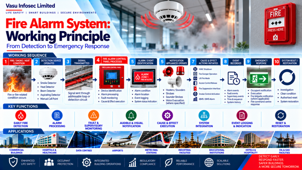
Fire / Smoke / Heat Condition → Detection Device Operates → Signal Transmitted → FACP Receives and Processes Signal → Alarm / Event Identification → Notification Appliances Operate → Approved Cause & Effect Functions Initiated → Event Recorded → Emergency Response → Authorised Reset / Restoration
This is a simplified sequence. The exact sequence and whether particular outputs operate depend on the system design and approved Cause & Effect Matrix.
3. Detection Principle
The detection layer identifies physical or environmental indicators associated with fire. Depending on the application, detection may be based on:
- Smoke particles
- Temperature rise
- Fixed temperature
- Flame radiation
- Aspirated air sampling
- Manual human initiation
- Specialised fire detection technologies
4. Signal Transmission
When a detector or manual call point operates, the initiating signal is transmitted through the applicable fire alarm circuit or addressable loop to the FACP. The transmission architecture should provide reliable communication and appropriate fault monitoring, in accordance with the approved design and selected equipment.
5. Fire Alarm Control Panel Processing
The FACP receives and processes incoming signals and determines the required system response. Typical functions may include:
- Device identification
- Alarm processing
- Fault monitoring
- Supervisory monitoring
- Event logging
- Notification control
- Cause & Effect execution
- System status indication
6. Alarm Initiation
An alarm condition is generated when the system receives an initiating input that meets the programmed criteria. Inputs may originate from:
- Automatic fire detector
- Manual call point
- Fire suppression interface, where approved
- Other approved fire alarm input
The response to each input must follow the approved design and Cause & Effect Matrix; not every input necessarily triggers identical outputs.
7. Notification Principle
Once an alarm condition is processed according to the approved system logic, notification appliances operate to alert occupants and relevant personnel. Notification may include:
- Audible sounders
- Hooters
- Visual strobes
- Sounder-strobes
- Voice evacuation systems, where specified
Notification selection and coverage must follow the approved fire strategy and project requirements.
8. Cause & Effect Operation
The Fire Alarm System may initiate additional actions based on the approved Cause & Effect Matrix. Typical actions include:
- HVAC shutdown
- Fire damper operation
- Lift fire mode
- Access control release
- Smoke control activation
- Fire suppression release interface
- IBMS / BMS alarm transmission
These actions must be coordinated with the responsible system parties and tested only against the approved interface requirements.
9. Fault and Supervisory Monitoring
The system monitors selected components and circuits for abnormal conditions. Typical monitored conditions may include:
- Open circuit
- Short circuit
- Device fault
- Panel fault
- Power supply failure
- Battery fault
- Communication fault
- Supervisory condition
The available monitoring functions depend on the selected equipment and system configuration. Fault and supervisory indications should be investigated and cleared in accordance with approved procedures.
10. Power Supply Principle
The Fire Alarm System requires a reliable power source to maintain operation. The power architecture generally includes:
- Primary power supply
- Fire alarm control equipment
- Auxiliary power supplies, where required
- Standby battery system
- Battery charging and monitoring
Battery capacity and standby duration must be calculated and verified against the approved design and applicable requirements.
11. Event Recording and Indication
Fire alarm events, faults and other programmed conditions may be recorded in the control panel event history. The system should clearly indicate, as applicable:
- Alarm condition
- Alarm location
- Fault condition
- Supervisory condition
- System status
- Event sequence
12. Reset and Restoration
After the emergency condition has been investigated and the system is confirmed safe to restore, authorised personnel may reset the system in accordance with the approved operating procedure. Reset is not proof that the underlying fire condition has been eliminated. Any persistent initiating condition should remain indicated until properly cleared.
13. Addressable System Working Principle
In an addressable system, individual field devices are assigned unique addresses. The FACP can identify the particular device or point associated with an event, supporting location identification, monitoring and diagnostics. The exact functions available depend on the selected system.
14. Conventional System Working Principle
In a conventional system, initiating devices are generally grouped into defined detection zones. When a device operates, the control panel identifies the affected zone rather than necessarily identifying the individual initiating device.
15. Integrated System Operation
Reliable operation depends on coordinated performance of detection devices, control equipment, notification appliances, power supplies and external interfaces. Engineering review should confirm:
- Correct device selection
- Proper installation
- Correct circuit configuration
- Approved Cause & Effect logic
- Adequate power backup
- Interface coordination
- Testing and commissioning
16. Testing and Commissioning
The working principle should be demonstrated through controlled testing under approved procedures. Testing may include:
- Detector operation
- Manual call point operation
- Alarm indication
- Notification appliance operation
- Fault simulation
- Input / output testing
- Cause & Effect testing
- Interface testing
- Battery testing
- Reset and restoration
Record test results, defects and outstanding actions in the project documentation.
17. Common Engineering Considerations
- Detection coverage
- Alarm response
- Signal transmission
- Panel processing
- Notification coverage
- Cause & Effect functions
- Fault monitoring
- Power backup
- Interface operation
- Event recording
18. Frequently Asked Questions
How does a fire alarm system work?
A detector or manual call point sends an initiating signal to the FACP. The panel processes it, operates the outputs defined by the approved logic and records the event.
What is the role of the FACP?
The FACP receives and processes inputs, identifies alarms and faults, controls notification and executes approved Cause & Effect functions.
Do all fire alarm signals activate every building interface?
No. Outputs depend on the approved Cause & Effect Matrix and system configuration.
What is the difference between addressable and conventional fire alarms?
Addressable systems generally identify individual devices, while conventional systems generally identify the affected zone.
Can a fire alarm system be reset immediately after an alarm?
Reset should be performed only by authorised personnel after the condition has been investigated and the approved restoration procedure has been followed.
Why are testing and maintenance important?
They help confirm that devices, circuits, notification appliances, power supplies and specified interfaces operate as intended.
19. Vasu Scope and Publication Guardrails
This article provides general engineering guidance. Vasu Infosec Limited’s responsibilities for a specific project must be established from the applicable Work Order, Purchase Order, BOQ, contract and approved specifications. Do not infer OEM design responsibility, third-party interface obligations, equipment performance guarantees or client/contractor responsibilities unless authorised project documents support them.
Client names, OEM details, project capacities, test results, completed-work claims and project outcomes must be published only after verification from approved records and confirmation that disclosure is authorised.
20. Technical Review and Publication Control
| Publication field | Required information |
| Author / Engineering Team | Vasu Infosec Limited |
| Technical Reviewer | To be assigned by the Engineering / Technical Department |
| Last Reviewed | Complete before publication |
| Applicable Standards / Editions | Verify against project design basis and AHJ requirements |
| References | Approved specifications, design documents, manufacturer documentation and applicable standards |
SEO Metadata – For Website CMS
| Field | Suggested content |
| SEO Title | How a Fire Alarm System Works | Vasu Infosec |
| Meta Description | Learn how fire alarm systems detect fire, transmit signals, process alarms, notify occupants, monitor faults and activate approved Cause & Effect functions. |
| Suggested URL Slug | /fire-alarm-system-working-principle/ |
| Primary Topic | Fire Alarm System Working Principle |
| Related Topics | Fire alarm detection; FACP; addressable vs conventional systems; Cause & Effect; testing and commissioning |
21. Engineering Objective
Reliable Detection → Accurate Signal Transmission → Correct Panel Processing → Timely Alarm Notification → Controlled Cause & Effect → Continuous Fault Monitoring → Reliable Power Backup → Verified Reset and Restoration → Effective Fire Alarm System Operation