
Article
Gas Suppression System: Complete Architecture
Oct 2026
Direct Answer
A gas suppression system combines fire detection, release controls, agent storage, distribution piping, discharge nozzles, and enclosure provisions to deliver the designed extinguishing agent concentration in a protected space. Its architecture and operating sequence must follow the approved system design, hazard assessment, manufacturer requirements, and applicable project requirements.
1. Engineering Overview
A Gas Suppression System is an engineered fire protection system that detects a developing fire and releases a gaseous extinguishing agent into a protected enclosure to control or suppress the fire. A complete system integrates fire detection, releasing control, agent storage, distribution piping, discharge nozzles, enclosure integrity, pressure relief, and associated safety interfaces.
2. Complete System Architecture
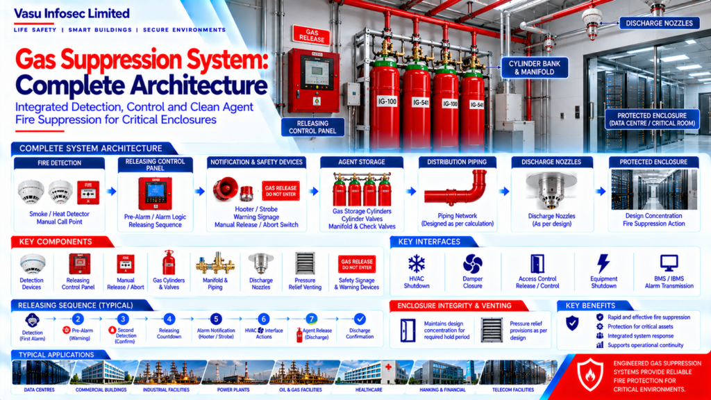
Protected Enclosure → Fire Detection Devices → Releasing Control Panel → Pre-Alarm / Alarm Logic → Releasing Sequence → Agent Storage Cylinders → Manifold / Valve Assembly → Distribution Piping → Discharge Nozzles → Design Concentration in Protected Space → Fire Suppression Action
3. Major System Components
A typical engineered gas suppression system may comprise:
- Fire detection devices
- Manual release station
- Abort/hold switch, where specified
- Releasing control panel
- Alarm notification appliances
- Gas storage cylinders
- Cylinder valves
- Manifold and check valves
- Pressure / supervisory devices
- Distribution piping
- Discharge nozzles
- Pressure relief venting
- Enclosure integrity provisions
- HVAC / access control interfaces
- Safety signage and warning devices
4. Fire Detection Layer
Automatic smoke, heat, or other approved detection devices provide the initiating signals for the suppression sequence. Detector selection and arrangement should follow the approved fire strategy, hazard characteristics and system design.
5. Releasing Control Layer
The releasing control panel receives detection inputs, evaluates the programmed releasing logic, and controls the suppression sequence. The panel should provide appropriate alarm, fault, supervisory, and release indications according to the approved system architecture.
6. Pre-Alarm & Release Sequence
A typical sequence may include:
Detection → First Alarm / Pre-Alarm → Second Confirmed Detection → Releasing Countdown → Audible / Visual Warning → HVAC / Interface Actions → Agent Release → Discharge Confirmation / System Status
7. Agent Storage Layer
The extinguishing agent is stored in approved cylinders selected for the required agent quantity, pressure, temperature range, and installation configuration. Cylinder capacity and quantity should be based on the approved system design.
8. Cylinder Bank & Manifold
Where multiple cylinders are required, cylinders may be connected through a manifold arrangement to provide coordinated discharge into the protected enclosure. The manifold assembly should include approved valves, connections, supports, and associated monitoring components.
9. Distribution Piping Network
The piping network distributes the extinguishing agent from the cylinder bank to the discharge nozzles. Pipe sizing, routing, fittings and configuration should be based on the approved hydraulic / flow calculation and manufacturer requirements.
10. Discharge Nozzles
Discharge nozzles distribute the agent within the protected enclosure. Nozzle type, orifice configuration, location and quantity should be determined from the approved system design and applicable manufacturer calculations.
11. Protected Enclosure
The protected room should provide the required enclosure conditions for the designed extinguishing concentration. Openings, doors, penetrations, dampers and other leakage paths should be considered during design and installation.
12. Enclosure Integrity
Room integrity is critical to maintaining the extinguishing agent concentration for the required hold period. The enclosure should be inspected and, where required, tested to identify excessive leakage and confirm suitability for the designed system.
13. Pressure Relief Venting
Agent discharge can create pressure changes within the protected enclosure. Pressure relief provisions should be designed where required to manage pressure effects while maintaining the required enclosure performance.
14. HVAC & Building Interfaces
The suppression system may interface with HVAC, dampers, access control, electrical systems, BMS / IBMS and other building services.
Typical actions may include:
- HVAC shutdown
- Damper closure
- Access-controlled door release/control
- Equipment shutdown
- Alarm transmission
- BMS / IBMS status indication
15. Safety & Warning Layer
The system should provide appropriate pre-discharge and discharge warnings, release status indication and safety signage in accordance with the approved design and applicable requirements. Manual release and abort functions should be provided where specified.
16. Testing & Commissioning
Complete system commissioning should verify:
- Detector operation
- Releasing logic
- Manual release
- Abort/hold function, where applicable
- Alarm notification
- Cylinder/valve status
- Interface operation
- Piping integrity
- Nozzle installation
- Cause & Effect sequence
- System reset and restoration
17. Common Engineering Considerations
Engineering review should verify:
- Correct suppression agent
- Hazard classification
- Protected volume
- Design concentration
- Agent quantity
- Cylinder configuration
- Piping network
- Nozzle arrangement
- Enclosure integrity
- Pressure relief requirements
- Cause & Effect logic
- Interface requirements
18. Documentation
Gas suppression system documentation should include, as applicable:
- System design basis
- Equipment datasheets
- Agent quantity calculation
- Cylinder schedule
- Manifold arrangement
- Piping drawings
- Hydraulic / flow calculation
- Nozzle schedule
- Cause & Effect Matrix
- Enclosure integrity test records
- FAT / SAT records
- Commissioning records
- As-built drawings
- O&M manual
19. Engineering Objective
The engineering objective is:
Reliable Fire Detection → Controlled Releasing Logic → Correct Agent Storage → Engineered Distribution Network → Effective Nozzle Discharge → Maintained Design Concentration → Controlled Pressure Effects → Verified Interfaces → Complete Commissioning → Reliable Gas Suppression Protection
Frequently Asked Questions
What are the main parts of a gas suppression system?
Typical components include detection devices, releasing controls, agent cylinders and valves, manifold, piping, nozzles, enclosure provisions, warnings, and approved building-system interfaces. The final configuration depends on the approved design.
How does the release sequence work?
A typical sequence may progress from detection and pre-alarm through confirmed detection, countdown, and warning to agent release. The actual sequence must follow the approved Cause & Effect Matrix and system design.
Why is enclosure integrity important?
The enclosure must support the designed extinguishing concentration for the required hold period. Leakage paths should be considered, and testing should be carried out where required.
Why may pressure relief be needed?
Agent discharge can create pressure changes in the protected space. Pressure-relief provisions should be designed where required based on the system and enclosure conditions.
What documents should be retained?
As applicable, records include the design basis, datasheets, agent quantity calculations, cylinder and nozzle schedules, piping drawings and flow calculations, Cause & Effect Matrix, enclosure integrity records, FAT/SAT and commissioning records, as-built drawings and O&M manual.
SEO & CMS Publication Metadata
| SEO title | Gas Suppression System Architecture: Components and Working |
| Meta description | Understand gas suppression system architecture, including detection, releasing controls, cylinders, piping, nozzles, enclosure integrity, interfaces, and commissioning. |
| Suggested URL slug | /gas-suppression-system-complete-architecture/ |
| Primary keyword | gas suppression system architecture |
| Related keywords | gas suppression system components; gaseous fire suppression system; releasing control panel; enclosure integrity; gas suppression commissioning |
| Suggested internal links | Fire Alarm System Architecture; Fire Alarm Cause & Effect Matrix; Fire Alarm FAT, SAT & Commissioning Flow; Fire Alarm Inspection, Testing & Maintenance Cycle |
Pre-Publication Technical Review
- Confirm the selected extinguishing agent and hazard classification against the approved design basis.
- Verify protected volume, design concentration, agent quantity, cylinder configuration, piping and nozzle calculations against approved manufacturer/project documents.
- Confirm enclosure integrity, hold-time requirements and pressure-relief provisions for the actual enclosure.
- Confirm the release sequence, abort/hold functions, warning arrangements and building-system interfaces against the approved Cause & Effect Matrix.
- Confirm testing responsibilities, acceptance requirements and document ownership before publication or project use.
- Add author, technical reviewer and review date only after approval.