
Case Study
FIRE ALARM SYSTEM DESIGN FOR A MULTI-STOREY COMMERCIAL BUILDING
Sep 2026
ENGINEERING DESIGN CASE CS-001
Fire Alarm System Design for a Multi-Storey Commercial Building
Linked Engineering Calculation: EC-001 – Smoke Detector Quantity & Spacing Calculation
PUBLICATION STATUS: ENGINEERING KNOWLEDGE EXAMPLE – NOT A VERIFIED CLIENT PROJECT
1. Engineering Background
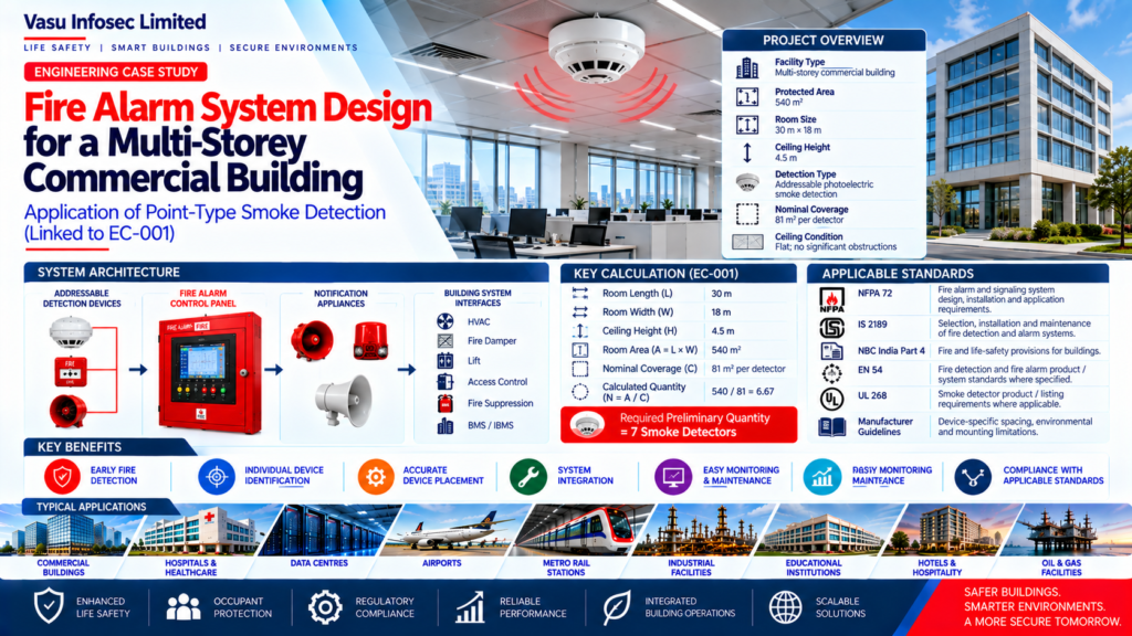
This engineering design case demonstrates a preliminary application of point-type smoke detection for a multi-storey commercial building. The design basis is derived from EC-001 and uses a protected area of 540 m², a flat ceiling at 4.5 m height and nominal detector coverage of 81 m² per detector. The example is intended to demonstrate engineering methodology, design considerations and verification steps. It is not presented as a record of a specific completed client project.
2. Facility / System Profile
| Parameter | Design Basis | Engineering Relevance |
| Facility Type | Multi-storey commercial building | Requires automatic fire detection and occupant notification. |
| Protected Area | 540 m² | Basis for preliminary detector quantity. |
| Room Geometry | 30 m × 18 m | Used to establish ceiling area. |
| Ceiling Height | 4.5 m | Requires verification of detector suitability and spacing. |
| Detection Type | Addressable photoelectric smoke detection | Provides individual device identification and event information. |
| Nominal Coverage | 81 m²/detector | Used only as the EC-001 preliminary calculation input. |
| Ceiling Condition | Flat; no significant obstructions assumed | Supports the preliminary area-based calculation. |
3. Engineering Challenge
The primary engineering challenge is to establish an initial detector quantity and arrangement without treating floor area as the only design parameter. Detector selection and spacing must also consider ceiling geometry, obstructions, airflow, HVAC discharge, manufacturer limitations and the requirements of the applicable fire alarm standard.
- Provide early fire detection across the protected space.
- Maintain device identification suitable for an addressable system.
- Avoid blind spots created by architectural or building-services coordination.
- Provide a design basis that can be developed into an approved reflected-ceiling layout.
4. Design Basis and Reference Standards
The EC-001 source identifies the following references as the design-review basis. Exact spacing, listed detector application, ceiling limitations and obstruction rules are to be checked against the applicable edition and project requirements for the final design.
| Reference | Application |
| NFPA 72 | Fire alarm and signaling system design, installation and application requirements. |
| IS 2189 | Selection, installation and maintenance of fire detection and alarm systems. |
| NBC India Part 4 | Fire and life-safety provisions for buildings. |
| EN 54 | Relevant fire detection and fire alarm product/system standards where specified. |
| UL 268 | Smoke detector product/listing requirements where applicable. |
| Manufacturer Installation Guidelines | Device-specific spacing, environmental and mounting limitations. |
5. Existing Conditions / Design Inputs
| Parameter | Symbol | Value | Unit |
| Room Length | L | 30 | m |
| Room Width | W | 18 | m |
| Ceiling Height | H | 4.5 | m |
| Room Area | A | 540 | m² |
| Nominal Detector Coverage | C | 81 | m²/detector |
| Detector Type | — | Photoelectric, addressable | — |
| Ceiling Type | — | Flat | — |
| Obstructions | — | None assumed | — |
6. Engineering Methodology
- Calculate the protected ceiling/floor area from room length and width.
- Apply the stated nominal detector coverage as the preliminary quantity calculation input.
- Divide the protected area by nominal coverage.
- Round the calculated quantity upward to the next whole device.
- Develop the physical layout separately using the applicable standard, ceiling geometry, obstruction rules and manufacturer data.
- Coordinate detector positions with HVAC, lighting, architectural elements, access panels and maintenance requirements.
- Validate the final design through device addressing, alarm testing, fault testing and integrated system testing.
7. Key Calculation and Design Parameters
The calculation follows the engineering basis documented in EC-001:
A = L × W = 30 × 18 = 540 m²
N = A / C = 540 / 81 = 6.67
Required preliminary quantity = 7 smoke detectors
This is a preliminary quantity only. It does not establish final device coordinates or final compliant spacing. Final spacing and detector application must be demonstrated on the approved layout against the applicable standard and manufacturer limitations.
8. System Architecture / Engineering Solution
- Addressable Fire Alarm Control Panel (FACP) as the primary system controller.
- Addressable photoelectric smoke detectors distributed across the protected area.
- Manual Call Points positioned as required by the approved life-safety design.
- Audible/visual notification appliances coordinated with occupant notification requirements.
- Supervisory and monitored interfaces for connected fire-protection systems where applicable.
- BMS/SCADA or other building-system interfaces implemented only through the approved cause-and-effect philosophy.
- Fire alarm event logging and individual device identification to support response and maintenance.
The engineering approach treats the fire alarm system as an integrated life-safety system rather than only a collection of detectors. The system may provide early detection, location identification, automatic control sequences and approved interfaces with suppression, smoke management, SCADA, BMS, access control and other systems, subject to the project cause-and-effect philosophy.
9. Vasu Engineering Capability Demonstrated
- Fire alarm system design methodology.
- Smoke detector quantity and spacing assessment.
- Addressable fire alarm system architecture.
- Cause-and-effect engineering and interface coordination.
- Architectural and MEP/HVAC coordination considerations.
- Testing, commissioning and integrated system verification.
- Engineering documentation, design review and checklist-based verification.
10. Coordination and Execution Challenges
- Final detector positions may shift when architectural and MEP drawings are coordinated.
- HVAC supply/return air locations can influence detector application and placement.
- Beams, bulkheads, cable trays and other obstructions can invalidate a simple area-based layout.
- Addressable loop capacity and device addressing must be coordinated with the selected FACP architecture.
- Cause-and-effect interfaces must be documented before programming and commissioning.
- False alarms can result from dust, steam, construction activity, unsuitable detector selection or poor maintenance.
11. Testing, Commissioning and Acceptance
- Verify device installation, identification and addressing.
- Verify addressable loop integrity and fault monitoring.
- Operate representative smoke detectors and verify alarm reporting at the FACP.
- Verify manual call point operation and notification appliance response.
- Test cause-and-effect sequences for all approved interfaces.
- Verify communication with BMS/SCADA or other interfaced systems where applicable.
- Perform integrated system testing under realistic emergency scenarios where practical.
12. Engineering Outcome
| Output | Result |
| Protected Area | 540 m² |
| Nominal Coverage | 81 m² per detector |
| Calculated Quantity | 6.67 |
| Preliminary Detector Quantity | 7 Nos. |
| Detection Technology | Addressable photoelectric smoke detection |
| Final Layout Status | Requires standard/manufacturer verification and multidisciplinary coordination |
13. Lessons Learned
- Area-based detector quantity is a useful preliminary design check but is not a substitute for compliant device spacing.
- Detector placement should be coordinated early with HVAC, architecture, lighting and ceiling services.
- Addressable architecture improves device identification, event logging and maintenance visibility.
- Cause-and-effect logic should be developed during design rather than left until commissioning.
- Integrated testing is necessary to demonstrate that fire alarm interfaces operate as one coordinated life-safety system.
- Maintenance and periodic revalidation are essential to preserve system reliability throughout the facility lifecycle.
14. Design Review Checklist
☐ Room geometry verified against latest architectural drawings
☐ Ceiling height and ceiling construction verified
☐ Detector application confirmed with manufacturer
☐ Detector spacing verified against applicable standard
☐ HVAC and airflow coordination completed
☐ Obstructions reviewed
☐ FACP loop/device capacity verified
☐ Cause-and-effect matrix approved
☐ Interface requirements documented
☐ Device addressing schedule prepared
☐ Testing and commissioning plan approved
☐ Integrated System Testing completed
15. Related Engineering Content
| Content Type | Reference |
| Engineering Calculation | EC-001 – Smoke Detector Quantity & Spacing Calculation |
| Related Domain | EC-002 to EC-020 – Fire Alarm Systems |
| Related White Paper | VEP-005 – Fire Alarm Systems and Integrated Fire Protection Engineering |
| Related Case Study | CS-002 – Addressable Fire Alarm Upgrade for an Operating Hospital |
| Related Diagram | ED-001 – Fire Alarm System Architecture / Detector Layout |
| Related FAQs | Fire Alarm Systems; Smoke Detector Selection; Addressable vs Conventional Fire Alarm; Cause-and-Effect Engineering |
16. Engineering References and Qualification
The quantitative design inputs and preliminary calculation in this engineering case are based on EC-001: 30 m × 18 m protected area, 4.5 m ceiling height, 540 m² area, 81 m² nominal detector coverage and seven preliminary smoke detectors. The broader engineering interpretation follows the supplied fire-alarm reference material concerning addressable device identification, event logging, diagnostics and system integration.
17. Publication Note
This document is an engineering knowledge example based on the stated design inputs and linked engineering calculation. It must not be represented as a completed client project or as evidence of project execution unless project-specific drawings, calculations, commissioning records, acceptance documentation and other supporting records are available.
Vasu Infosec Limited