
Case Study
Fire Alarm System Integration with BMS in a Commercial Facility
Nov 2026
Direct Engineering Answer
This illustrative case study explains the engineering considerations for fire alarm system integration with bms in a commercial facility. The design approach should be developed from the approved fire strategy, facility conditions, applicable project requirements and the selected manufacturer’s verified technical data. Any layouts, quantities, calculations, interfaces and commissioning criteria shown in this knowledge example require project-specific review and approval before implementation.
1. Project Background
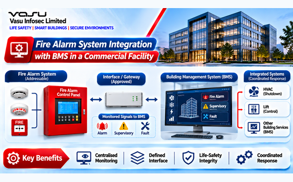
This case study presents an illustrative engineering approach for integrating an addressable fire alarm system with a Building Management System (BMS) in a commercial facility. The objective is to provide the BMS operator with reliable fire alarm, supervisory and fault information while ensuring that fire alarm life-safety functions remain under the approved fire alarm architecture. The case is prepared for the engineering knowledge library and is not presented as a verified record of a specific completed project.
2. Facility / System Profile
| Parameter | Design Basis | Engineering Relevance |
| Facility | Multi-storey commercial facility | Centralised monitoring of multiple building services. |
| Fire Alarm | Addressable fire alarm control panel | Provides alarm, supervisory and fault status. |
| BMS | Central building management platform | Receives approved fire-related monitoring information. |
| Interface | Hardwired monitored interface / approved gateway | Provides defined signal exchange between systems. |
| Monitoring Points | Fire alarm common alarm, supervisory and fault signals | Supports operator awareness. |
| Life-Safety Control | Fire alarm remains the authoritative life-safety controller | Prevents BMS from becoming an unapproved substitute for fire alarm logic. |
3. Engineering Challenge
The principal engineering challenge is to establish a reliable boundary between the fire alarm system and BMS. The BMS should receive the information necessary for building operation and monitoring, while critical fire alarm decisions and life-safety sequences remain controlled by the approved fire alarm system and its cause-and-effect logic.
- Define exactly which fire alarm signals are transmitted to BMS.
- Prevent unauthorised BMS commands from affecting fire alarm life-safety functions.
- Maintain clear signal priority and fail-safe behaviour.
- Coordinate fire alarm, HVAC and BMS interface responsibilities.
- Provide a controlled basis for programming and integrated testing.
- Maintain traceability between the fire alarm matrix, BMS point list and final as-built documentation.
4. Engineering Basis and Applicable References
The supplied fire alarm engineering framework identifies NFPA 72, IS 2189, NBC India Part 4, EN 54, UL 268 and manufacturer installation guidance as applicable references. The actual BMS interface method must also comply with the selected fire alarm manufacturer’s listed interface architecture and the project’s approved controls philosophy.
| Reference | Engineering Application |
| NFPA 72 | Fire alarm system design, supervision, control and testing. |
| IS 2189 | Fire detection and alarm system selection, installation and maintenance. |
| NBC India Part 4 | Building fire and life-safety provisions. |
| EN 54 | Relevant fire alarm product/system requirements where specified. |
| UL 268 | Smoke detector listing requirements where applicable. |
| Manufacturer Data | Fire alarm panel, interface module, gateway and communication characteristics. |
5. Existing Conditions / Assessment Basis
- The commercial facility contains a central BMS serving HVAC, electrical and other building services.
- The fire alarm system is an addressable architecture with monitored events.
- The BMS requires fire-related status information for operator awareness and building-service coordination.
- Critical fire alarm control functions remain within the approved fire alarm system.
- Interface signal ownership and responsibilities are defined before installation and programming.
6. Engineering Methodology
- Review the approved fire strategy and fire alarm cause-and-effect matrix.
- Identify fire alarm signals that must be displayed or monitored by BMS.
- Define the interface method and signal type for each point.
- Prepare a fire alarm-to-BMS point list with unique tags.
- Confirm whether each point is alarm, supervisory, trouble/fault or status information.
- Define communication failure and interface fault monitoring requirements.
- Coordinate BMS graphics and alarm priorities with the fire alarm event hierarchy.
- Test each point from field device to fire alarm panel, interface and BMS workstation.
- Complete Integrated System Testing for all approved cross-system functions.
7. Illustrative Fire Alarm-to-BMS Point List
The following point list demonstrates a typical engineering structure. Actual points must be taken from the approved fire strategy and project requirements; no generic interface should be assumed as mandatory.
| Point | Source | BMS Indication | Signal Type | Verification |
| FA-ALM-01 | Fire Alarm Panel | Common Fire Alarm | Alarm | Initiate detector/MCP test. |
| FA-SUP-01 | Fire Alarm Panel | Common Supervisory | Supervisory | Initiate approved supervisory condition. |
| FA-FLT-01 | Fire Alarm Panel | Common Fire Fault | Fault | Create controlled fault condition. |
| FA-STA-01 | Fire Alarm Panel | System Healthy | Status | Verify normal condition. |
| FA-ZONE-01 | Fire Alarm Panel | Fire Zone Alarm | Alarm | Test representative zone input. |
8. Engineering Solution
- Use a controlled interface between the fire alarm system and BMS.
- Transmit only approved fire alarm information required for monitoring and building-service coordination.
- Maintain fire alarm cause-and-effect logic within the fire alarm system.
- Use clear point naming conventions matching the fire alarm device and zone database.
- Provide alarm priorities and operator graphics consistent with the emergency response philosophy.
- Monitor communication/interface health where required by the selected architecture.
- Maintain a controlled interface schedule linking drawings, panel programming and BMS database.
9. HVAC and Building-Service Coordination
Fire alarm and BMS integration becomes particularly important where fire alarm events affect HVAC or smoke-management equipment. The supplied reference framework identifies interfaces with smoke management, BMS/SCADA and other building systems as part of integrated fire protection engineering. The actual response must be taken from the approved cause-and-effect matrix rather than assumed as a universal shutdown sequence.
| Interface | Engineering Consideration | Acceptance Test |
| AHU / HVAC | Fire alarm may initiate an approved operating mode or shutdown. | Alarm-to-HVAC response test. |
| Smoke Control | Fire alarm may initiate approved smoke-control sequence. | Integrated sequence test. |
| BMS Graphics | Alarm and fault status displayed with correct priority. | Point-to-point verification. |
| Operator Acknowledgement | BMS acknowledgement must not replace fire alarm reset authority. | Functional verification. |
| Communication Link | Loss of interface should be identifiable where supervised. | Communication/fault test. |
10. Programming, Testing and Commissioning
- Verify the approved fire alarm point list.
- Verify each physical interface module and cable termination.
- Confirm correct signal mapping at the fire alarm panel.
- Confirm correct BMS point mapping and graphics.
- Test alarm, supervisory, fault and normal conditions.
- Verify alarm priorities and operator annunciation.
- Test approved HVAC and smoke-management sequences.
- Verify interface communication failure indication where applicable.
- Perform Integrated System Testing and record all results.
11. Engineering Outcome
| Outcome | Engineering Result |
| Interface Architecture | Controlled fire alarm-to-BMS interface. |
| Monitoring | Approved alarm, supervisory, fault and status information available to BMS. |
| Life-Safety Authority | Fire alarm system remains the primary life-safety controller. |
| HVAC Coordination | Approved fire-related HVAC sequences coordinated through the cause-and-effect matrix. |
| Documentation | Point list, graphics, interface drawings and testing records aligned. |
| Acceptance | Point-to-point and integrated interface testing completed. |
12. Lessons Learned
- BMS should not be treated as a replacement for the dedicated fire alarm control system.
- Interface points must be defined from the approved fire strategy and cause-and-effect matrix.
- Signal naming consistency is essential for commissioning and long-term maintenance.
- Alarm, supervisory and fault conditions should have distinct priorities and operator indications.
- Interface failures should be identifiable where the project architecture requires supervision.
- Integrated testing is necessary because correct point mapping alone does not prove the complete emergency sequence.
- Any change to fire alarm or BMS programming should be controlled through formal revision management.
13. Design Review Checklist
☐ Approved fire strategy reviewed
☐ Fire alarm cause-and-effect matrix approved
☐ Fire alarm-to-BMS point list prepared
☐ Signal types and priorities confirmed
☐ Interface hardware/gateway verified
☐ BMS graphics approved
☐ HVAC interface responsibilities defined
☐ Communication fault monitoring reviewed
☐ Fire alarm reset authority confirmed
☐ Point-to-point testing completed
☐ Integrated System Testing completed
☐ Final point database and as-built documentation updated
14. Related Engineering Content
| Content Type | Reference |
| Engineering Calculations | EC-001 to EC-020 – Fire Alarm Systems; EC-006 – Fire Alarm System Integration with BMS |
| Related Case Studies | CS-001 – Multi-Storey Commercial Building; CS-002 – Operating Hospital; CS-003 – Data Centre Coverage; CS-004 – High-Rise Cause-and-Effect; CS-005 – Metro Station Loop Distribution |
| Related White Paper | VEP-005 – Fire Alarm Systems and Integrated Fire Protection Engineering |
| Related FAQs | Fire Alarm to BMS Integration; Cause-and-Effect Matrix; BMS Fire Alarm Interface; Integrated System Testing |
| Related Engineering Diagram | ED-006 – Fire Alarm and BMS Integration Architecture |
15. Source Basis and Engineering Qualification
The case-specific commercial facility, point list and interface examples are illustrative engineering assumptions created for the knowledge-library format. They are not claimed as project-recorded facts. Final interface design shall be based on approved drawings, the fire strategy, manufacturer data, authority requirements and the project cause-and-effect matrix.
Website Publication Metadata
Suggested SEO Page Title: Fire Alarm System Integration with BMS in a Commercial Facility | Vasu Infosec
Suggested Meta Description: Engineering considerations for fire alarm system integration with bms in a commercial facility, including design basis, coordination, verification and project-specific technical review.
Suggested URL Slug: fire-alarm-system-integration-with-bms-in-a-commercial-facility
Primary Search Keyword: fire alarm system integration with bms