
Q&A
Gas Suppression Systems
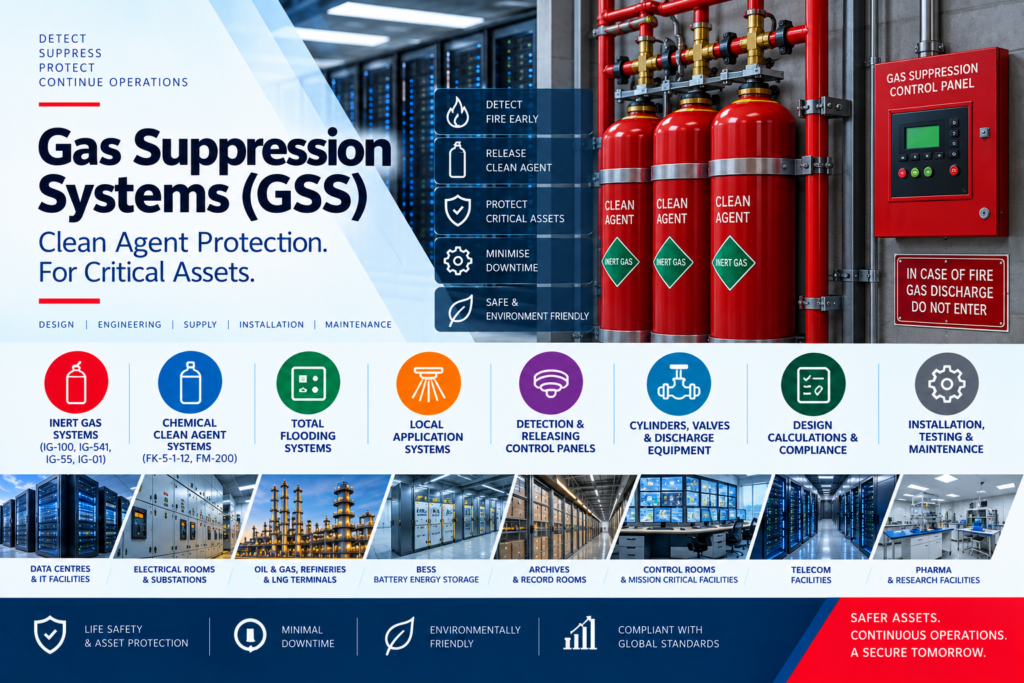
A Gas Suppression System (GSS) is a fixed fire protection system that extinguishes fires using clean gaseous extinguishing agents without damaging sensitive equipment. It is primarily used to protect critical assets where water-based systems are unsuitable.
Gas Suppression Systems extinguish fires without leaving residue or causing water damage to electronic equipment, documents, and valuable assets. They are ideal for areas where business continuity and equipment protection are critical.
Gas Suppression Systems extinguish fire by reducing oxygen concentration, absorbing heat, or interrupting the chemical chain reaction of combustion, depending on the extinguishing agent used. The fire is suppressed without damaging protected equipment.
Clean agent systems are classified into Inert Gas Systems (IG-100, IG-541, IG-55, IG-01) and Chemical Clean Agent Systems (FK-5-1-12 and HFC-227ea/FM-200). The selection depends on the application, hazard type, occupancy, and project specifications.
Inert gas systems extinguish fire by lowering oxygen concentration to a level that stops combustion while remaining safe for occupants. Chemical clean agents primarily absorb heat and interrupt the combustion process using significantly smaller storage volumes.
A Total Flooding System discharges the extinguishing agent throughout the entire protected enclosure to achieve the required extinguishing concentration. It is commonly used in enclosed spaces such as data centres, server rooms, electrical rooms, and control rooms.
A Local Application System discharges the extinguishing agent directly onto a specific hazard without filling the entire enclosure. It is used for protecting localized equipment where total flooding is impractical.
Gas Suppression Systems are primarily designed for Class A (surface fires), Class B (flammable liquids), and Class C (energized electrical equipment). The suitability depends on the clean agent used and the applicable fire protection standards.
Gas Suppression Systems require enclosed spaces with adequate room integrity to maintain the extinguishing concentration. They are generally ineffective for deep-seated fires, reactive metals, and hazards involving self-oxidizing materials.
A Gas Suppression System consists of storage cylinders, control valves, actuators, discharge nozzles, piping network, Fire Alarm/Releasing Control Panel, detectors, manual release station, abort switch, pressure relief damper, and alarm devices working together to detect and suppress fire.
IG-541 (Inergen) is an inert gas mixture of 52% Nitrogen, 40% Argon, and 8% Carbon Dioxide. It suppresses fire by reducing oxygen concentration below the combustion level while the added CO₂ stimulates human breathing, making it suitable for occupied spaces.
IG-100 is a 100% nitrogen-based clean agent that extinguishes fire by reducing oxygen concentration without leaving residue. It is widely used in data centres, electrical rooms, substations, archives, and industrial facilities requiring environmentally friendly fire protection.
IG-55 (Argonite) is a blend of 50% Argon and 50% Nitrogen that suppresses fire by reducing oxygen concentration. It is environmentally safe, electrically non-conductive, leaves no residue, and has zero ozone depletion and global warming potential.
IG-01 consists of 100% Argon gas and extinguishes fire by lowering the oxygen concentration below the combustion threshold. It is non-toxic, non-corrosive, electrically non-conductive, and suitable for protecting sensitive electronic equipment.
FK-5-1-12 is a fluorinated ketone clean agent that extinguishes fire by rapidly absorbing heat from the flame. It leaves no residue, is electrically non-conductive, has low atmospheric lifetime, and is commonly used as a replacement for phased-out clean agents where specified.
HFC-227ea (FM-200) is a chemical clean agent that suppresses fire primarily by absorbing heat and interrupting combustion. It is widely used in server rooms, UPS rooms, control rooms, museums, and telecommunication facilities requiring rapid fire suppression.
IG-541 is an inert gas system that reduces oxygen concentration and requires larger storage cylinders, whereas FM-200 is a chemical clean agent that extinguishes fire mainly through heat absorption and requires less storage space. The selection depends on project requirements, environmental considerations, and available room space.
Inert gas systems discharge nitrogen, argon, or their mixtures to lower oxygen concentration to approximately 12–15%, which suppresses combustion while remaining safe for short-term human exposure in accordance with applicable standards.
Chemical clean agents extinguish fire by rapidly absorbing heat and disrupting the combustion chain reaction without significantly reducing oxygen levels. This enables fast suppression while minimizing damage to sensitive equipment.
Extinguishing concentration is determined through standardized fire testing based on the hazard class, fuel type, enclosure conditions, and selected clean agent. Design concentrations are established in accordance with NFPA 2001, ISO standards, and OEM hydraulic calculation software.
A Gas Suppression System is designed by evaluating the fire hazard, protected enclosure, agent type, design concentration, room volume, and applicable standards. The design includes cylinder sizing, hydraulic calculations, nozzle placement, detection logic, and control system integration.
Enclosure integrity is the ability of a protected room to retain the extinguishing agent at the required concentration for the specified hold time. Poor room integrity can result in agent leakage and ineffective fire suppression.
A Door Fan Integrity Test (DFIT) measures the leakage characteristics of a protected enclosure using a calibrated fan. It verifies whether the room can maintain the required agent concentration for the minimum hold time without conducting an actual gas discharge.
Hold time is calculated based on room leakage, enclosure volume, agent concentration, and environmental conditions using approved software or testing methods. Most systems require the extinguishing concentration to be maintained for at least 10 minutes or as specified by the applicable standard.
Pressure relief dampers protect the enclosure from excessive positive or negative pressure generated during agent discharge. They prevent structural damage while maintaining the required room integrity and safe pressure limits.
Cylinder sizing is determined by the protected room volume, design concentration, discharge pressure, storage temperature, and selected extinguishing agent. OEM hydraulic calculation software is used to ensure the required quantity of agent is available.
Hydraulic calculations determine the correct pipe sizes, pressure losses, flow rates, and nozzle discharge characteristics to ensure uniform agent distribution. Calculations are performed using OEM-approved software in accordance with NFPA 2001 and manufacturer requirements.
Discharge time depends on the extinguishing agent, cylinder pressure, pipe diameter, pipe length, nozzle design, and hydraulic losses. Most clean agent systems are designed to complete discharge within 10 seconds as required by applicable standards.
Discharge nozzles are selected based on the agent type, flow rate, room geometry, and hydraulic calculations. They are positioned to provide uniform agent distribution and achieve the required extinguishing concentration throughout the protected enclosure.
Cable routing should be mechanically protected, fire-resistant where required, and separated from power cables to avoid interference. Actuator circuits must be continuously monitored for open and short circuits and comply with the releasing panel and OEM design requirements.
Gas Suppression Systems are integrated with the Fire Alarm System through a releasing control panel that receives signals from fire detectors. Upon confirmed fire detection, the system initiates alarms, shutdowns, discharge delays, and automatic agent release according to the approved Cause-and-Effect Matrix.
Cross-zone detection requires two independent detectors or detection zones to activate before releasing the extinguishing agent. This reduces false discharges while ensuring reliable fire confirmation before suppression begins.
The abort switch temporarily delays automatic agent discharge while it is pressed, allowing personnel to safely evacuate or investigate. The manual release switch enables immediate discharge of the extinguishing agent during an emergency when automatic operation is not sufficient.
A discharge delay, typically 20–60 seconds, provides sufficient time for occupants to evacuate and allows verification of the fire condition. It also ensures all pre-discharge alarms and system shutdowns are completed before releasing the extinguishing agent.
Before agent discharge, the Gas Suppression System automatically shuts down HVAC equipment and closes dampers to prevent agent leakage. This helps maintain the required extinguishing concentration within the protected enclosure.
Fire dampers, smoke dampers, and ventilation openings are automatically closed before agent release to seal the enclosure. Pressure relief dampers operate during discharge to control room pressure without compromising enclosure integrity.
Integration with BMS and SCADA enables centralized monitoring of alarms, faults, cylinder status, discharge events, and system health. Communication is typically achieved using protocols such as BACnet, Modbus, or other OEM-approved interfaces.
A Cause-and-Effect Matrix defines the sequence of actions initiated by fire detection, including alarm activation, HVAC shutdown, damper closure, discharge delay, agent release, and status monitoring. It serves as the basis for programming and commissioning the releasing control panel.
The sequence typically includes fire detection, cross-zone confirmation, audible and visual alarms, HVAC shutdown, damper closure, discharge delay, agent release, discharge confirmation, and post-discharge monitoring. All actions must follow the approved Cause-and-Effect Matrix.
Gas Suppression Systems rapidly extinguish fires without damaging sensitive equipment, minimizing downtime and enabling faster recovery of critical operations. They are widely used in data centres, control rooms, telecom facilities, and electrical installations where uninterrupted service is essential.
Commissioning includes functional testing of detectors, releasing panels, manual release and abort switches, actuator circuits, alarms, HVAC interfaces, Cause-and-Effect logic, and cylinder supervision. Room Integrity Testing (Door Fan Test) and integrated system testing are also carried out before handover.
Cylinders should be inspected for hydrostatic test validity, pressure gauge readings, physical damage, identification labels, agent quantity, valve assembly, discharge hoses, and manufacturer certifications. Installation should comply with approved drawings and OEM guidelines.
Gas Suppression Systems should be inspected regularly in accordance with NFPA 2001, IS standards, and OEM recommendations. Routine maintenance includes checking cylinder pressure, releasing devices, detectors, control panels, piping, nozzles, and room integrity.
Common failures include cylinder pressure loss, actuator malfunction, detector faults, leaking pipe joints, damaged nozzles, wiring faults, control panel failures, and poor enclosure integrity. Regular inspection and preventive maintenance help identify and rectify these issues.
Unwanted discharge can be prevented by implementing cross-zone detection, discharge delay timers, monitored actuator circuits, protected manual release stations, abort switches, and proper maintenance. System programming and periodic testing also reduce accidental activations.
Occupants should evacuate immediately upon pre-discharge alarm, and warning signs, manual release stations, abort switches, and emergency exits should remain accessible. Personnel should only re-enter the protected area after it has been declared safe and adequately ventilated.
Gas Suppression Systems are governed by NFPA 2001, NFPA 72, ISO 14520, EN 15004, IS 15493, IS 2189, and the National Building Code (NBC) of India. Compliance with project specifications and OEM requirements is also essential.
Consultants typically require approved OEM authorization, UL/FM or equivalent certifications (where specified), hydraulic calculations, room integrity reports, Cause-and-Effect Matrix, battery calculations, compliance statements, commissioning procedures, and similar project experience for technical evaluation.
Interview questions commonly cover clean agent selection, inert gas versus chemical systems, hydraulic calculations, room integrity testing, cross-zone detection, releasing panel logic, commissioning procedures, applicable standards, and practical troubleshooting of Gas Suppression Systems.
Future Gas Suppression Systems will focus on environmentally sustainable clean agents, AI-assisted monitoring, IoT-enabled diagnostics, predictive maintenance, digital twins, and enhanced integration with Building Management Systems. New technologies aim to improve fire protection while reducing environmental impact and lifecycle costs.