
Q&A
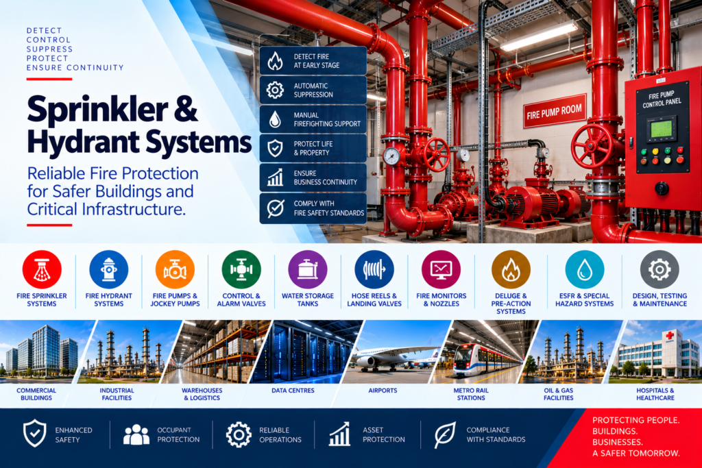
Sprinkler & Hydrant Systems
A Fire Sprinkler System is an automatic water-based fire suppression system that detects heat from a fire and discharges water through sprinkler heads to control or extinguish the fire at its early stage.
A Fire Hydrant System is a fixed firefighting water distribution network comprising hydrants, landing valves, hose reels, pumps, and piping that enables trained personnel or firefighters to manually combat fires.
These systems provide immediate and reliable firefighting capability, limit fire growth, protect occupants and property, reduce business interruption, and support emergency response while complying with fire safety regulations.
The objectives are to detect and control fires quickly, protect life and property, minimize fire damage, support evacuation, assist firefighting operations, and maintain business continuity.
Major components include sprinkler heads, piping network, control valves, alarm valves, flow switches, pressure gauges, Fire Pumps, jockey pumps, water storage tanks, and system controllers.
A Fire Hydrant System consists of Fire Pumps, underground and overhead fire water storage tanks, hydrant mains, landing valves, hose reels, fire hoses, branch pipes, hydrant pillars, breeching inlets, valves, and fittings.
Sprinkler Systems operate automatically when sprinkler heads are exposed to fire, whereas Fire Hydrant Systems require manual operation by trained personnel using hoses and hydrant outlets.
The main types are Wet Pipe, Dry Pipe, Pre-Action, Deluge, Early Suppression Fast Response (ESFR), and Residential Sprinkler Systems, each designed for specific fire hazards and environmental conditions.
Fire Hydrant Systems include Wet Riser Systems, Dry Riser Systems, Internal Hydrant Systems, External Hydrant Networks, Yard Hydrants, and Combined Hydrant-Sprinkler Systems based on building type and fire risk.
During a fire, sprinkler heads automatically discharge water onto the affected area, while hydrant systems supply high-pressure water through hoses for manual firefighting. Fire Pumps maintain the required flow and pressure throughout the system.
Automatic sprinkler heads operate individually when the heat-sensitive element, such as a glass bulb or fusible link, reaches its rated temperature. This releases water directly onto the fire, controlling or suppressing it at the point of origin.
Common sprinkler heads include pendent, upright, sidewall, concealed, ESFR (Early Suppression Fast Response), CMSA (Control Mode Specific Application), residential, and extended coverage sprinklers. Selection depends on occupancy, ceiling configuration, and fire hazard.
Pendent sprinklers are installed below ceilings, upright sprinklers above piping, sidewall sprinklers along walls, concealed sprinklers provide an aesthetic finish, and ESFR sprinklers are designed for rapid suppression of high-challenge storage fires.
Standard Response (SR) sprinklers operate at a normal activation speed, while Quick Response (QR) sprinklers have faster thermal sensitivity, enabling earlier water discharge and improved occupant protection in life safety applications.
Temperature ratings are selected based on the maximum expected ambient temperature of the protected area. The sprinkler activation temperature should be sufficiently above normal operating conditions to prevent unwanted operation.
Hazard classifications are determined by evaluating occupancy type, fire load, combustible materials, storage arrangement, ceiling height, and operational activities. Common classifications include Light Hazard, Ordinary Hazard (Group 1 & 2), and Extra Hazard (Group 1 & 2).
Sprinkler spacing is determined by hazard classification, sprinkler type, discharge characteristics, ceiling configuration, obstructions, and the maximum coverage area permitted by applicable design standards.
Ceiling height influences sprinkler selection, spacing, operating pressure, discharge pattern, and hydraulic demand. High ceilings may require specialized sprinklers such as ESFR or in-rack systems for effective fire control.
Hydraulic calculations determine the required flow rate, pressure, pipe sizes, friction losses, and Fire Pump capacity using the hydraulically most demanding design area in accordance with applicable standards.
Common mistakes include incorrect hazard classification, inadequate hydraulic calculations, improper sprinkler spacing, obstruction of discharge patterns, incorrect temperature ratings, insufficient water supply, and failure to coordinate with architectural and MEP services.
A Fire Hydrant System is designed based on occupancy hazard, building layout, fire water demand, coverage requirements, hydrant locations, hydraulic calculations, and applicable fire protection standards to ensure adequate flow and pressure.
A wet riser is permanently filled with pressurized water and is commonly used in high-rise buildings, whereas a dry riser remains empty until charged by the fire service during an emergency and is typically used in medium-rise buildings where permitted by local regulations.
Landing valves are selected based on pressure rating, flow capacity, connection size, and applicable standards. They are installed at designated floor levels within fire shafts or staircases to provide safe access for firefighting operations.
Hose reels provide an immediately accessible water supply for occupants or trained personnel to control small fires during the initial stages before the arrival of the fire service.
Breeching inlets allow the fire service to supplement the building's fire water supply by pumping water into wet or dry riser systems when the installed water source is insufficient or unavailable.
Internal hydrants are located within buildings to provide coverage of occupied areas, while external hydrants are positioned around the site perimeter and roadways to provide access for firefighting vehicles and outdoor fire protection.
Hydrant mains are sized using hydraulic calculations that consider required flow rate, operating pressure, friction losses, elevation differences, pipe material, and simultaneous hydrant operation under the most demanding conditions.
Fire water distribution networks are typically designed as looped or ring main systems to provide reliable water supply, balanced pressure distribution, operational flexibility, and redundancy during maintenance or emergency conditions.
High-rise buildings require zoned riser systems, pressure management, and adequate Fire Pump capacity, while industrial facilities require extensive external hydrant networks, monitor systems, and sufficient fire water storage based on hazard assessment.
Common mistakes include inadequate hydrant coverage, incorrect pipe sizing, insufficient Fire Pump capacity, poor valve accessibility, inadequate water storage, excessive pressure losses, and failure to coordinate with site layout and emergency vehicle access.
Fire Pumps provide the required flow and pressure to sprinkler and hydrant networks during fire emergencies. A typical installation includes electric, diesel, and jockey pumps operating through automatic controllers to ensure uninterrupted water supply.
Fire Water Storage Tanks are sized based on the total firefighting water demand, required discharge duration, simultaneous operation of fire protection systems, and applicable codes. Underground, overhead, or compartmentalized tanks may be provided.
Jockey pumps maintain system pressure by compensating for minor leakage and pressure fluctuations. They prevent unnecessary operation of the main Fire Pumps during normal conditions.
Pressure zones are established using zoned piping, pressure-reducing valves (PRVs), break tanks, and booster Fire Pumps to maintain safe operating pressures throughout the building while preventing excessive pressure at lower floors.
Fire Alarm Systems monitor sprinkler flow switches, valve supervisory switches, pressure switches, and Fire Pump controllers. Alarm signals are transmitted to the Fire Alarm Control Panel for annunciation, monitoring, and emergency response.
BMS monitors Fire Pump status, tank water levels, valve positions, alarms, faults, pressure conditions, and supervisory signals. This enables centralized monitoring and facility management without overriding fire system priorities.
The Cause-and-Effect Matrix defines the automatic sequence of operations initiated by sprinkler activation or hydrant-related alarms, including Fire Pump starting, alarm annunciation, BMS notification, HVAC shutdown (where applicable), and emergency communication.
These systems control or suppress fires during their early stages, protect occupants, minimize property damage, reduce operational downtime, and provide firefighters with a dependable water supply for emergency response.
The System Integrator coordinates the engineering, installation, programming, testing, and commissioning of Fire Alarm, Sprinkler, Hydrant, Fire Pump, BMS, SCADA, and other life safety systems to ensure seamless interoperability.
Engineering calculations include hydraulic calculations, fire water demand, Fire Pump sizing, storage tank capacity, pipe sizing, friction loss analysis, pressure zoning, flow requirements, and network performance verification in accordance with applicable standards.
Installation shall comply with approved shop drawings, OEM instructions, project specifications, and applicable standards. Piping, sprinklers, hydrants, valves, supports, and Fire Pumps shall be installed with proper alignment, accessibility, corrosion protection, labeling, and seismic support where required.
FAT verifies Fire Pumps, pump controllers, valves, pressure switches, monitoring devices, control panels, and associated equipment for performance, compliance with specifications, and proper operation before shipment.
SAT includes hydrostatic pressure testing, pipeline flushing, flow testing, hydrant discharge testing, sprinkler alarm testing, Fire Pump performance testing, valve operation verification, pressure measurement, and integrated system functionality checks.
Commissioning includes inspection of completed installations, verification of hydraulic performance, Fire Pump operation, alarm interface testing, Cause-and-Effect validation, documentation review, operator training, and final acceptance testing.
Preventive maintenance includes regular inspection of sprinklers, hydrants, valves, Fire Pumps, piping, hose reels, pressure gauges, tanks, supervisory devices, and alarm interfaces. Periodic flow testing and pump performance testing are also required.
Common failures include closed control valves, pump malfunction, inadequate water pressure, blocked sprinklers or hydrants, pipe corrosion, leakage, damaged gauges, and alarm interface failures. Diagnosis is performed through inspections, hydraulic testing, flow tests, and system diagnostics.
Sprinkler & Hydrant Systems are designed and maintained in accordance with NFPA 13, NFPA 14, NFPA 20, NFPA 24, NFPA 25, IS 15105, IS 13039, IS 15325, NBC India, and project-specific consultant or authority requirements.
Consultants typically require hydraulic calculations, Fire Pump calculations, water storage calculations, approved OEM products, UL/FM or equivalent certifications where specified, shop drawings, QA/QC documentation, FAT/SAT procedures, commissioning methodology, and evidence of similar project experience.
Interview questions commonly cover hazard classification, sprinkler spacing, hydraulic calculations, Fire Pump selection, hydrant network design, wet and dry risers, Fire Water Storage Tanks, NFPA and IS standards, commissioning procedures, and Cause-and-Effect integration.
Future developments include IoT-enabled valve and pressure monitoring, smart sprinkler technology, AI-assisted hydraulic analysis, Digital Twin integration, predictive maintenance, cloud-based Fire Pump monitoring, and intelligent fire water management systems. These innovations improve system reliability, operational efficiency, and lifecycle performance.