
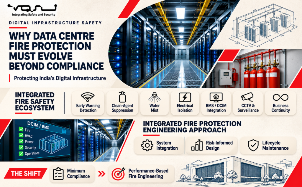
Whitepaper
Why Data Centre Fire Protection Must Evolve Beyond Compliance
Nov 2026
Executive Summary
India is undergoing one of the fastest expansions of digital infrastructure in the world. Government cloud initiatives, Digital India, hyperscale cloud providers, financial institutions, telecom operators, defence establishments and public sector enterprises are investing billions of rupees in new data centres. These facilities are expected to operate continuously, delivering availability levels that often exceed 99.995%.
In this environment, fire protection can no longer be viewed as a statutory requirement or an isolated package within a construction contract. A single fire event can interrupt banking transactions, government services, telecommunications, healthcare systems and national digital infrastructure within minutes.
The traditional approach of selecting individual products based solely on compliance certificates is no longer sufficient. Modern data centres demand an engineering approach that integrates early warning detection, clean agent suppression, water mist protection for utility areas, electrical isolation, HVAC controls, Building Management Systems (BMS), Data Centre Infrastructure Management (DCIM), SCADA, cybersecurity and lifecycle maintenance into one coordinated protection strategy.
International standards such as NFPA 75, NFPA 76, NFPA 2001, NFPA 855, TIA-942, FM Global Data Sheets and the Uptime Institute provide valuable guidance. However, every data centre presents unique challenges arising from power density, lithium-ion battery installations, operational continuity requirements, climatic conditions and local regulatory frameworks.
This paper argues that India’s next generation of data centres should move beyond prescriptive compliance toward performance-based fire engineering, where the objective is not merely extinguishing fires but ensuring uninterrupted business continuity, protecting mission-critical assets and safeguarding human life.
—
Chapter 1
India’s Digital Infrastructure Revolution
India’s digital economy is expanding at an unprecedented pace. Cloud computing, artificial intelligence, digital payments, e-governance and industrial automation are driving demand for resilient data centres across the country.
Large-scale investments are being made by:
Government cloud programmes
Public Sector Undertakings
Banking and financial institutions
Telecom operators
Hyperscale cloud providers
Colocation providers
Defence and strategic organizations
Healthcare networks
Manufacturing enterprises
Unlike conventional commercial buildings, a data centre is designed for uninterrupted operation. Even a brief interruption can result in significant financial loss, regulatory exposure and reputational damage.
Consequently, fire protection objectives extend beyond life safety. They also include:
Protection of critical digital assets
Preservation of business continuity
Minimisation of service disruption
Protection of high-value electrical equipment
Rapid restoration following an incident
These objectives require a fundamentally different engineering philosophy.
—
Why Data Centres Are Different
The fire risk profile of a modern data center differs significantly from that of conventional buildings.
A typical facility contains:
High-density server racks
UPS systems
Lithium-ion battery rooms
Electrical switchgear
Cable trays and raised floors
HVAC infrastructure
Diesel generator systems
Fuel storage
Transformers
Network operation centres
Each subsystem presents distinct fire hazards and interacts with the others.
For example:
A fire originating within a UPS battery room may require immediate electrical isolation, clean agent discharge, HVAC shutdown, smoke extraction, alarm verification and notification to the BMS and DCIM platforms—all within seconds.
Treating these systems as independent packages creates operational risk.
They must instead be engineered as an integrated life-safety ecosystem.
—
The Cost of Downtime
Industry studies consistently show that the cost of an unplanned data centre outage can reach millions of dollars per incident, depending on the size and criticality of the facility.
The direct costs include:
Business interruption
Service unavailability
Equipment replacement
Recovery operations
Regulatory penalties
Contractual liabilities
Indirect costs may include:
Loss of customer confidence
Brand damage
Legal disputes
Data recovery efforts
Delayed public services
For mission-critical facilities, the engineering objective is therefore business continuity, not simply fire extinguishment.
—
Engineering Perspective
A compliant fire protection system does not necessarily guarantee a resilient data centre.
Resilience depends on how effectively detection, suppression, power systems, HVAC, controls and operational procedures function together under emergency conditions.
This paper examines how those systems should be engineered, integrated, tested and maintained to support the next generation of India’s digital infrastructure.
—
Next: Chapter 2 – Fire Dynamics and Risk Profile of Modern Data Centres, covering lithium-ion batteries, server racks, cable fires, electrical faults, hidden ignition sources and lessons from major international data center fire incidents.
Chapter 2
Fire Dynamics and Risk Profile of Modern Data Centres
Understanding Where Fires Start—and Why They Spread
—
> Engineering Insight
Most data centre fires do not begin in the server racks. They originate in the supporting infrastructure that enables continuous operation.
—
2.1 Introduction
Modern data centres are often perceived as “low fire risk” environments because they contain limited combustible building materials and operate under tightly controlled conditions.
This assumption is misleading.
While large flaming fires inside server halls are relatively uncommon, electrical faults, battery failures, overheating equipment, cable insulation breakdown and human intervention create credible ignition sources throughout the facility.
The engineering challenge is therefore not simply suppressing a fire after it develops, but detecting abnormal conditions early enough to prevent escalation.
—
2.2 The Anatomy of a Data Centre
A typical Tier III or Tier IV data centre consists of multiple interconnected risk zones, each with distinct fire hazards.
White Space (Server Hall)
Contains:
Server racks
Network switches
Storage arrays
Fibre distribution
Underfloor cabling
Primary risks:
Power supply failures
Overheated components
Electrical arcing
Cable insulation failure
—
UPS Rooms
Contains:
UPS modules
Battery banks
Power distribution equipment
Primary risks:
Battery thermal runaway
DC faults
Internal UPS failures
High fault currents
—
Battery Rooms
Increasingly equipped with:
Lithium-ion batteries
VRLA batteries
Nickel-based systems
Key risks include:
Thermal runaway
Re-ignition
Toxic gas release
High-temperature propagation
Battery rooms now represent one of the fastest-growing fire engineering challenges in mission-critical infrastructure.
—
Electrical Rooms
Contain:
MV switchgear
LV switchgear
PCCs
MCCs
Bus ducts
Transformers
Typical ignition sources:
Loose connections
Insulation degradation
Arc flash
Equipment failure
—
DG Generator Areas
Risks include:
Diesel fuel
Lubricating oil
Hot exhaust systems
Mechanical failures
Unlike server halls, these spaces may require water-based suppression strategies.
—
Cable Basements and Cable Galleries
These areas often contain:
High cable density
Vertical cable shafts
Communication infrastructure
Power feeders
Cable fires can spread rapidly if detection is delayed.
—
2.3 Common Causes of Data Centre Fires
Fire investigations around the world consistently identify several recurring causes.
Electrical Faults
The most common cause.
Includes:
Short circuits
Overloaded conductors
Poor terminations
Insulation failure
Loose busbar joints
—
Battery Failures
Particularly relevant with:
Lithium-ion systems
Battery Energy Storage Systems (BESS)
Possible initiating events include:
Internal cell failure
Charging faults
Manufacturing defects
Mechanical damage
—
Human Error
Examples:
Maintenance activities
Improper cable installation
Accidental damage
Incorrect electrical isolation
Hot work
—
Mechanical Failure
Includes:
Bearing failures
Cooling fan malfunction
Motor overheating
Pump failures
These events often generate heat long before flames become visible.
—
2.4 Fire Development Inside a Data Centre
Unlike warehouse fires, data center fires frequently begin as small electrical events.
Typical progression:
Stage 1
Component overheating
↓
Stage 2
Insulation degradation
↓
Stage 3
Smoke generation
↓
Stage 4
Electrical arcing
↓
Stage 5
Open flame
↓
Stage 6
Fire propagation
↓
Stage 7
Smoke contamination
↓
Stage 8
Operational shutdown
This sequence demonstrates why early warning detection is far more valuable than relying solely on suppression systems.
—
2.5 Smoke: The Hidden Threat
In mission-critical facilities, smoke often causes greater operational damage than flames.
Smoke contamination can:
Damage electronic components.
Corrode circuit boards.
Contaminate storage media.
Trigger equipment shutdown.
Affect HVAC systems.
Spread rapidly through raised floors and ceiling voids.
Even a minor fire can require extensive cleaning, testing and equipment replacement before systems return to service.
—
2.6 Lithium-Ion Batteries
The rapid adoption of lithium-ion batteries is transforming data center fire engineering.
Advantages include:
Higher energy density
Reduced footprint
Longer service life
Faster recharge
However, they also introduce new fire challenges.
Thermal runaway can produce:
Extremely high temperatures
Flammable gases
Re-ignition
Cell-to-cell propagation
Traditional suppression systems alone may not prevent thermal runaway once initiated.
Engineering must therefore priorities:
Early detection
Battery monitoring
Ventilation
Gas detection
Emergency response planning
—
2.7 Business Continuity vs Fire Suppression
Historically, fire protection focused on extinguishing fires.
Modern data centres require a broader objective:
Maintaining operational continuity.
This means protecting:
Data availability
Network connectivity
Critical applications
Financial transactions
Government services
Cloud platforms
Engineering decisions should therefore be evaluated against their impact on service continuity, not merely fire extinguishment.
—
2.8 Lessons from International Incidents
Investigations into major data center fire incidents consistently highlight common themes:
Delayed detection.
Electrical failures.
Smoke migration beyond the fire area.
Inadequate compartmentation.
Poor integration between HVAC and fire systems.
Insufficient emergency procedures.
Very few failures result from the absence of suppression systems.
Most result from failures in engineering integration.
—
2.9 Engineering Implications
Every identified risk influences the design of:
Detection philosophy
Clean agent selection
Water mist application
Battery protection
HVAC control logic
Electrical isolation
BMS integration
DCIM integration
SCADA interfaces
Emergency response procedures
These systems cannot be engineered independently.
—
Chapter 2 – Key Engineering Takeaways
Data centre fires often originate in electrical and support infrastructure rather than server racks.
Early detection is the most effective method of limiting damage.
Smoke contamination may cause greater operational loss than flames.
Lithium-ion batteries require specialized engineering strategies beyond conventional suppression.
Business continuity should be the primary design objective.
Fire protection must be integrated with electrical systems, HVAC, BMS, DCIM and operational procedures.
—
Engineering Quote
> “In a mission-critical facility, the first objective is not simply to extinguish the fire. It is to ensure that critical digital services remain available—or are restored with minimal interruption.”
—
Next Chapter: Performance-Based Fire Engineering for Data Centres – Moving Beyond Code Compliance to Business Resilience, where we will examine how international standards, design fire scenarios, risk assessments and integrated engineering shape the protection of modern mission-critical facilities.
Chapter 3
Performance-Based Fire Engineering for Data Centres
Designing for Business Continuity, Not Just Code Compliance
—
> Engineering Insight
A compliant data centre is not necessarily a resilient data centre. Compliance demonstrates that minimum requirements have been met; performance-based engineering demonstrates that the facility can continue to protect life, critical assets and business operations during credible fire scenarios.
—
3.1 Why Compliance Alone Is No Longer Enough
For many years, fire protection design in data centres has focused on satisfying statutory requirements and applicable standards.
Typical design questions included:
Which standard applies?
What type of suppression system is required?
How many detectors are required?
What clean agent concentration is needed?
How long should the agent be retained?
These questions remain important.
However, they do not answer the most important question:
> Can this data center continue to support critical operations during and after a fire?
Performance-Based Fire Engineering (PBFE) addresses this question by evaluating how the entire facility performs under realistic fire scenarios rather than simply verifying compliance with prescriptive requirements.
—
3.2 What Is Performance-Based Fire Engineering?
Performance-Based Fire Engineering is an engineering methodology that defines measurable performance objectives and demonstrates, through analysis and validation, that those objectives will be achieved.
For a data centre, the objectives typically include:
Protection of human life.
Protection of mission-critical equipment.
Limitation of fire spread.
Reduction of smoke contamination.
Maintenance of business continuity.
Rapid restoration after an incident.
Protection of high-value digital assets.
The focus shifts from “What system should be installed?” to “How should the facility perform during a fire?”
—
3.3 Defining the Design Fire
Every performance-based design begins by identifying credible fire scenarios.
A single “worst-case fire” is rarely sufficient.
Different areas of a data centre require different design assumptions.
Typical scenarios include:
Scenario 1 – Server Rack Fire
Potential causes:
Power supply failure
Overheated components
Internal electrical faults
Engineering priorities:
Early smoke detection
Clean agent discharge
HVAC shutdown
Smoke containment
—
Scenario 2 – UPS Failure
Potential causes:
Internal component failure
DC fault
Capacitor failure
Engineering priorities:
Electrical isolation
Early warning detection
Clean agent protection
Equipment redundancy
—
Scenario 3 – Lithium-Ion Battery Thermal Runaway
Potential causes:
Cell failure
Charging malfunction
Mechanical damage
Engineering priorities:
Gas detection
Temperature monitoring
Ventilation management
Emergency response procedures
Prevention of propagation
—
Scenario 4 – Cable Gallery Fire
Potential causes:
Cable insulation failure
Overloaded circuits
Mechanical damage
Engineering priorities:
Linear heat detection
Smoke management
Fire compartmentation
Electrical isolation
—
Scenario 5 – Diesel Generator Fire
Potential causes:
Fuel leaks
Hot exhaust components
Mechanical failure
Engineering priorities:
Water mist or suitable suppression
Fuel isolation
Ventilation control
Emergency shutdown
Each scenario requires different engineering responses, yet all must operate within one integrated protection philosophy.
—
3.4 Designing for Business Continuity
Traditional fire engineering often concludes when the fire has been extinguished.
Mission-critical facilities require a broader perspective.
Questions that must be considered include:
How quickly can IT services be restored?
Which systems remain operational during suppression?
Can unaffected areas continue functioning?
How is smoke prevented from contaminating adjacent halls?
How will redundant systems support ongoing operations?
The objective is not merely to stop the fire but to minimize operational disruption.
—
3.5 Risk Assessment
Performance-Based Fire Engineering relies on structured risk assessment rather than assumptions.
Factors typically evaluated include:
Equipment criticality.
Fire load density.
Electrical fault potential.
Occupancy.
Redundancy.
HVAC configuration.
Battery technology.
Fuel storage.
Maintenance practices.
External hazards.
The findings influence every major design decision.
—
3.6 Integration of Engineering Disciplines
Fire protection cannot be designed independently.
Successful PBFE requires collaboration between:
Fire engineers.
Electrical engineers.
Mechanical engineers.
HVAC specialists.
ICT designers.
BMS engineers.
DCIM specialists.
Security engineers.
Structural engineers.
Operations teams.
Each discipline contributes to the overall resilience of the facility.
—
3.7 Engineering Validation
Performance-Based Fire Engineering requires evidence that the proposed design will achieve its objectives.
Typical validation methods include:
Fire modelling.
Smoke movement analysis.
CFD simulations.
Detection response analysis.
Hydraulic calculations.
Clean agent concentration calculations.
Battery hazard analysis.
Cause-and-effect verification.
Integrated testing.
Engineering decisions should be supported by documented analysis rather than assumptions alone.
—
3.8 Failure Mode Analysis
Mission-critical facilities must continue operating even when individual components fail.
Typical failure scenarios include:
Detector failure.
Suppression valve malfunction.
UPS failure.
Fan failure.
Communication network outage.
BMS server failure.
Power supply interruption.
Operator error.
The engineering objective is to ensure that no single failure compromises the overall protection strategy.
This philosophy aligns with the redundancy principles used throughout Tier III and Tier IV data centres.
—
3.9 Commissioning Is an Engineering Process
Commissioning should demonstrate that every subsystem performs correctly—not only individually but also as part of an integrated emergency response.
Testing should include:
Early warning detection.
Fire alarm verification.
HVAC shutdown.
Clean agent discharge logic.
Electrical isolation.
BMS integration.
DCIM alarms.
SCADA interfaces.
Emergency communications.
Manual override functions.
Only integrated testing confirms that the facility will perform as intended during a real emergency.
—
3.10 The System Integrator’s Perspective
From a System Integrator’s perspective, Performance-Based Fire Engineering is the framework that unifies all protection systems.
The System Integrator ensures that:
Detection initiates the correct sequence.
HVAC responds appropriately.
Clean agent systems discharge safely.
Water mist protects utility areas where applicable.
Electrical systems isolate affected equipment.
BMS and DCIM receive real-time information.
Operators receive clear, actionable alarms.
Every interface is tested and documented.
Without this integration, individual systems may comply with standards while the facility as a whole remains vulnerable.
—
Chapter 3 – Key Engineering Takeaways
Performance-Based Fire Engineering focuses on measurable facility performance rather than minimum compliance.
Different areas of a data centre require different design fire scenarios.
Business continuity is a primary engineering objective.
Fire protection must be integrated with power, HVAC, BMS, DCIM and operational procedures.
Validation through modelling, calculations and integrated testing is essential.
The System Integrator plays a central role in translating engineering intent into reliable operational performance.
—
Engineering Quote
> “The success of a data centre fire protection strategy is not measured by how much equipment is installed. It is measured by how effectively the facility continues to protect people, preserve critical assets and sustain operations when an emergency occurs.”
—
Next Chapter: Early Warning Fire Detection – VESDA, Aspirating Smoke Detection, AI Video Analytics, Linear Heat Detection and Multi-Criteria Detection in Modern Data Centres, where we will examine how early detection is the single most important factor in reducing fire damage and maintaining business continuity.
Chapter 4
Early Warning Fire Detection
Detecting a Fire Before It Becomes a Business Disaster
—
> Engineering Insight
In a mission-critical data centre, the objective is not to detect flames—it is to detect the conditions that lead to flames. Every minute gained before ignition can save hours or even days of operational downtime.
—
4.1 Why Early Detection Matters
A conventional office building may tolerate a delay of several minutes before a fire is detected.
A data centre cannot.
Modern servers, storage arrays, UPS systems and communication equipment operate continuously, often under high electrical loads. A fault may begin with microscopic insulation damage or overheating inside a power supply, producing minute quantities of combustion particles long before visible smoke or flames appear.
If detected at this stage, operators may isolate the equipment, investigate the fault and restore normal operation without any interruption to business services.
If detection occurs only after flames develop, the consequences can include:
Equipment loss
Smoke contamination
Clean agent discharge
Service interruption
Costly recovery operations
Extended downtime
Early warning detection is therefore one of the highest-value investments in mission-critical fire protection.
—
4.2 The Stages of Fire Development
A fire rarely begins with flames.
In most data centres, it develops progressively:
Stage 1 – Incipient Stage
Component overheating
Insulation degradation
Microscopic combustion particles
No visible smoke
This is the ideal point for intervention.
—
Stage 2 – Smouldering Stage
Light smoke
Increasing heat
Electrical insulation decomposition
Odour generation
—
Stage 3 – Flaming Stage
Visible flames
Rapid temperature increase
Smoke production
Potential fire spread
—
Stage 4 – Fully Developed Fire
Extensive equipment involvement
High temperatures
Smoke migration
Business interruption
The engineering objective is to identify the fire during Stage 1 or Stage 2, well before open flames occur.
—
4.3 Aspirating Smoke Detection (VESDA)
Aspirating Smoke Detection (ASD), commonly referred to by the well-known VESDA technology, has become the benchmark for early warning detection in data centres.
The system continuously draws air through a network of sampling pipes and analyses it using highly sensitive optical detectors capable of identifying extremely low concentrations of smoke particles.
Advantages
Extremely early warning
Continuous air sampling
High sensitivity
Adjustable alarm thresholds
Suitable for clean environments
Supports staged alarm philosophy
Typical Applications
Server halls
UPS rooms
Battery rooms
Network operation centres
Raised floors
Ceiling voids
ASD provides valuable time for operators to investigate abnormal conditions before suppression systems are activated.
—
4.4 Multi-Level Alarm Philosophy
One of the strengths of aspirating detection is the ability to implement graduated alarm levels.
A typical sequence may include:
Alert
Minor increase in airborne particles.
Action:
Notify operators.
Begin investigation.
—
Action
Smoke concentration increasing.
Action:
Dispatch engineering personnel.
Review CCTV.
Inspect affected equipment.
—
Fire 1
Confirmed abnormal condition.
Action:
Initiate emergency procedures.
Prepare suppression systems.
Notify control room.
—
Fire 2
Confirmed fire.
Action:
Activate suppression sequence.
Shut down HVAC where required.
Initiate equipment isolation.
This staged approach reduces false discharges while maintaining rapid response capability.
—
4.5 Point-Type Smoke Detectors
Point smoke detectors remain useful in many auxiliary spaces.
Typical applications include:
Offices
Control rooms
Corridors
Support areas
Storage rooms
Advantages:
Cost-effective
Simple installation
Easy maintenance
Limitations:
Slower response in high airflow environments
Limited coverage
Less effective in very clean spaces
Point detectors should complement—not replace—early warning aspirating systems within critical areas.
—
4.6 Heat Detection
Heat detectors respond only after temperatures exceed predefined thresholds.
Typical applications:
Generator rooms
Mechanical spaces
Electrical plant rooms
Utility areas
Advantages:
High reliability
Resistant to dust
Low false alarm rates
Limitations:
Late response
Unsuitable for early warning in server halls
Heat detection should therefore be used selectively, based on the risk profile of each area.
—
4.7 AI Video Analytics
Artificial Intelligence is increasingly being integrated with CCTV systems.
Modern video analytics can identify:
Smoke
Flames
Equipment overheating (with thermal cameras)
Human activity
Restricted area access
Benefits include:
Visual verification
Faster operator response
Reduced nuisance alarms
Support for remote monitoring
AI analytics should enhance situational awareness rather than replace conventional fire detection systems.
—
4.8 Detection in High-Airflow Environments
One of the unique challenges in data centres is the presence of powerful cooling systems.
High airflow can:
Dilute smoke
Delay smoke reaching ceiling detectors
Alter smoke movement
Reduce detector effectiveness
Engineering solutions include:
Aspirating detection
Underfloor sampling
Ceiling void sampling
Rack-level detection where justified
CFD-supported detector placement
Detector locations should be determined through engineering analysis rather than standard spacing rules alone.
—
4.9 Integration with Building Systems
Fire detection is only valuable if it initiates the correct operational response.
Upon confirmation of a fire, detection systems should interface with:
Fire Alarm Control Panel
BMS
DCIM
SCADA
HVAC controls
Electrical isolation systems
Clean agent release panels
Access control
Emergency communication systems
The cause-and-effect logic should be documented, tested and validated during commissioning.
—
4.10 The System Integrator’s Perspective
From the perspective of a System Integrator, fire detection is not an isolated package—it is the trigger for the entire emergency response.
The System Integrator must ensure that:
Detection zones align with suppression zones.
Alarm priorities are correctly configured.
HVAC responds according to design intent.
BMS and DCIM receive accurate status information.
CCTV automatically displays affected areas.
Operators receive clear and actionable alarms.
False alarm management is robust.
All interfaces are verified during integrated testing.
The quality of this integration determines whether early warning translates into effective incident management.
—
Chapter 4 – Key Engineering Takeaways
Early warning detection is essential for protecting mission-critical facilities.
Aspirating Smoke Detection provides the earliest practical indication of developing fire conditions.
Multi-level alarm strategies improve response while reducing unnecessary discharges.
High-airflow environments require specialised detector selection and placement.
AI video analytics enhance verification and operator awareness.
Detection systems must be fully integrated with BMS, DCIM, SCADA, HVAC and suppression systems.
The value of early detection lies not only in sensing smoke, but in initiating a coordinated engineering response.
—
Engineering Quote
> “In a data centre, the best fire is the one that never reaches the flame stage. Early warning detection gives engineers the opportunity to intervene before a technical fault becomes a business crisis.”
—
Next Chapter: Clean Agent Fire Suppression Systems – IG-541, Inert Gases, FK-5-1-12 Alternatives, Design Principles and Business Continuity, including room integrity testing, discharge philosophy, environmental considerations and integration with mission-critical infrastructure.
Chapter 5
Clean Agent Fire Suppression Systems
Protecting Mission-Critical Assets Without Damaging Them
—
> Engineering Insight
The objective of a clean agent system is not simply to extinguish a fire. It is to suppress the fire while preserving the integrity, availability and recoverability of mission-critical infrastructure.
—
5.1 Why Water Is Not Always the Right Solution
Water is one of the most effective fire suppression media for many occupancies. However, in a data centre, indiscriminate water discharge can create damage comparable to—or greater than—the fire itself.
A modern server hall may contain:
High-density server racks
Blade servers
Storage arrays
Core network switches
Optical fibre infrastructure
High-value electronics
While these systems are designed to tolerate controlled environmental conditions, they are not intended to withstand unnecessary water exposure.
For this reason, data centres rely primarily on clean agent suppression systems for occupied IT spaces, while reserving water-based systems for utility and mechanical areas where appropriate.
—
5.2 What Is a Clean Agent?
A clean agent is a gaseous fire suppression medium that:
Leaves no residue after discharge.
Is electrically non-conductive.
Does not damage sensitive electronic equipment.
Suppresses fire rapidly.
Allows faster restoration of operations.
Unlike water-based systems, clean agents extinguish fire without requiring extensive post-discharge cleaning of electronic equipment.
This characteristic makes them particularly suitable for:
Server halls
Network Operation Centres (NOCs)
UPS control rooms
Telecom rooms
Command and Control Centres
Mission-critical IT spaces
—
5.3 Types of Clean Agent Systems
Modern data centres commonly use two broad categories of clean agents.
Inert Gas Systems
Typical examples include:
IG-541
IG-55
IG-100
These systems extinguish fire by reducing the oxygen concentration within the protected enclosure to a level that prevents combustion while remaining safe for short-term human exposure under designed conditions.
Advantages
Zero ozone depletion.
Extremely low global warming impact.
Long service life.
Naturally occurring gases.
Suitable for long-term sustainability objectives.
Considerations
Larger cylinder storage.
Higher storage pressure.
Strong emphasis on room integrity.
—
Chemical Clean Agents
Historically these included agents such as FK-5-1-12 and HFC-based suppressants.
They suppress fire primarily through heat absorption and interruption of combustion chemistry.
Advantages
Lower storage volume.
Rapid discharge.
Well suited to smaller protected enclosures.
Considerations
Environmental regulations continue to evolve.
Future availability may be influenced by international policy changes.
Designers should monitor developments regarding fluorinated compounds and sustainability requirements.
Engineering decisions should therefore consider not only current compliance but also long-term environmental and regulatory trends.
—
5.4 Why IG-541 Is Gaining Importance
Many government facilities, financial institutions and hyperscale operators are increasingly evaluating inert gas systems such as IG-541 because of their long-term environmental profile.
Typical applications include:
National Data Centres
Banking Infrastructure
Defence Installations
Government Cloud Facilities
Mission-Critical Control Rooms
IG-541 consists of naturally occurring gases and leaves no decomposition residue after discharge.
Its environmental characteristics align well with long asset life cycles expected in critical infrastructure.
—
5.5 Designing a Clean Agent System
A clean agent system is far more than a cylinder bank connected to discharge nozzles.
Successful performance depends upon:
Accurate hazard volume calculations.
Leakage assessment.
Nozzle hydraulic calculations.
Pipe network design.
Flow calculations.
Discharge time verification.
Pressure relief provisions.
Detection logic.
Electrical interlocks.
HVAC control.
Room integrity.
Every component influences overall system effectiveness.
—
5.6 Room Integrity Testing
One of the most overlooked aspects of clean agent performance is room integrity.
Even the best suppression system cannot achieve its design objective if the enclosure cannot retain the extinguishing concentration for the required duration.
Potential leakage paths include:
Cable penetrations.
Pipe sleeves.
Raised floor openings.
Ceiling voids.
Door gaps.
HVAC dampers.
Structural joints.
Door Fan Integrity Testing should therefore be considered an essential engineering validation rather than a contractual formality.
Room integrity should also be re-evaluated whenever significant building modifications occur.
—
5.7 Detection Before Discharge
A clean agent should never discharge based on a single detector activation.
Modern systems generally employ a cross-zoned detection philosophy, requiring confirmation from independent detection signals before initiating automatic release.
Typical sequence:
1. Early warning (ASD/VESDA).
2. Investigation alarm.
3. Confirmed fire (cross-zone).
4. Audible and visual pre-discharge warning.
5. Time delay for evacuation.
6. HVAC shutdown.
7. Door and damper control.
8. Electrical isolation where applicable.
9. Clean agent discharge.
10. Post-discharge monitoring.
This sequence minimises unnecessary discharges while ensuring rapid suppression of genuine fire events.
—
5.8 Integration with Mechanical and Electrical Systems
A clean agent system cannot operate effectively in isolation.
Before discharge, coordinated actions are typically required:
HVAC shutdown.
Fire damper closure.
Electrical isolation of affected equipment.
Access control release where appropriate.
Notification to BMS.
Notification to DCIM.
SCADA event logging.
Operator confirmation.
Failure to coordinate these systems may significantly reduce suppression effectiveness.
—
5.9 Business Continuity Considerations
From a business continuity perspective, suppression success is measured by more than extinguishment.
Questions include:
Can unaffected data halls remain operational?
How quickly can the protected room return to service?
Was smoke migration prevented?
Was unnecessary equipment shutdown avoided?
Were redundant systems maintained?
Were recovery procedures documented?
Engineering decisions should therefore support operational resilience as well as fire suppression.
—
5.10 The System Integrator’s Perspective
The System Integrator is responsible for ensuring that the clean agent system functions as part of one coordinated protection strategy.
Typical responsibilities include:
Integration of ASD, point detection and fire alarm panels.
Cross-zone logic verification.
Interface with HVAC controls.
Electrical shutdown coordination.
BMS and DCIM integration.
SCADA monitoring.
Door release and access control interfaces.
Cause-and-effect testing.
Integrated Site Acceptance Testing (SAT).
Operator training and documentation.
The performance of a clean agent system depends as much on these interfaces as it does on the suppression agent itself.
—
Chapter 5 – Key Engineering Takeaways
Clean agent systems protect mission-critical equipment without leaving damaging residues.
Inert gas systems such as IG-541 offer strong environmental credentials and are increasingly adopted for critical infrastructure.
Successful suppression depends on hydraulic design, room integrity, detection philosophy and system integration.
Door Fan Integrity Testing is essential to verify enclosure performance.
Cross-zoned detection reduces false discharges while maintaining rapid response.
Business continuity should remain the primary engineering objective.
The System Integrator ensures that suppression, detection, HVAC, electrical systems, BMS, DCIM and SCADA operate as one coordinated life-safety ecosystem.
—
Engineering Quote
> “A clean agent cylinder does not protect a data centre by itself. Protection is achieved only when detection, room integrity, HVAC, electrical isolation, controls and suppression operate as a single engineered system.”
—
Next Chapter: High-Pressure Water Mist for Data Centres – Utility Areas, Transformers, Diesel Generators, Battery Energy Storage Systems (BESS) and Electrical Infrastructure, explaining where water mist is appropriate, where it is not, and how it complements clean agent protection in an integrated mission-critical facility.
Chapter 6
High-Pressure Water Mist for Data Centres
Engineering the Right Protection for Utility and Critical Infrastructure
—
> Engineering Insight
High-Pressure Water Mist is not a replacement for clean agent systems. It is a complementary engineering solution designed to protect those areas where gaseous suppression may not be practical, economical or technically appropriate.
—
6.1 The Most Common Misconception
One of the most common misconceptions in data center fire protection is that a single suppression technology can protect the entire facility.
In reality, a modern mission-critical data center consists of multiple fire zones, each with different hazards and operational requirements.
For example:
Area Preferred Protection Philosophy
Server Hall Clean Agent
Network Rooms Clean Agent
UPS Electronics Clean Agent
Transformer Yard Water Mist
Diesel Generator Rooms Water Mist
Fuel Pump Rooms Water Mist
Cable Galleries Water Mist / Hybrid Approach
Battery Energy Storage Systems (BESS) Risk-Based Design
Mechanical Plant Rooms Water Mist
The engineering objective is technology selection based on hazard, not standardization around a single suppression medium.
—
6.2 Why Water Mist?
High-Pressure Water Mist produces extremely fine water droplets at operating pressures typically ranging from 80 to 140 bar.
Unlike conventional sprinklers, Water Mist is designed to maximise cooling efficiency while significantly reducing water consumption.
Its principal fire suppression mechanisms include:
Rapid heat absorption.
Cooling of flames and hot gases.
Reduction of radiant heat.
Localised oxygen displacement through steam generation.
Limitation of fire spread.
For utility spaces containing electrical and mechanical equipment, these characteristics make Water Mist an attractive engineering option.
—
6.3 Transformer Protection
Transformers represent one of the highest fire-risk assets within many data centres.
Potential ignition sources include:
Insulation failure.
Internal electrical faults.
Bushings.
Oil leaks.
External flashover.
A transformer fire can rapidly escalate because of:
Large quantities of insulating oil.
High radiant heat.
Potential fire spread to adjacent transformers or buildings.
High-Pressure Water Mist provides:
Rapid cooling.
Reduction of radiant heat.
Exposure protection.
Limitation of fire spread.
System design should consider:
Transformer geometry.
Wind conditions (for outdoor installations).
Oil containment.
Electrical clearances.
Drainage.
Environmental regulations.
—
6.4 Diesel Generator Rooms
Emergency generators are essential for business continuity.
However, they introduce fire hazards including:
Diesel fuel.
Lubricating oil.
Hot engine surfaces.
Exhaust systems.
Fuel transfer pumps.
Water Mist is particularly effective in generator rooms because it:
Controls Class B fuel fires.
Reduces compartment temperatures.
Protects structural components.
Allows manual firefighting to begin under improved conditions.
Engineering design must integrate Water Mist with:
Fuel shut-off valves.
Generator shutdown logic.
Ventilation control.
Fire detection.
Emergency alarms.
—
6.5 Battery Energy Storage Systems (BESS)
The rapid deployment of Battery Energy Storage Systems introduces one of the most complex fire engineering challenges in modern data centres.
Unlike conventional electrical fires, lithium-ion battery incidents involve:
Thermal runaway.
Internal chemical reactions.
Flammable gas release.
Re-ignition.
Cell-to-cell propagation.
Water Mist should not be viewed as a universal solution for every battery chemistry.
Engineering decisions should be based upon:
Battery type.
Manufacturer guidance.
International testing.
Hazard analysis.
Performance objectives.
In many installations, Water Mist forms part of a layered protection strategy together with:
Early gas detection.
Temperature monitoring.
Smoke detection.
Ventilation.
Emergency isolation.
Fire-resistant compartmentation.
—
6.6 Cable Galleries and Utility Tunnels
Cable galleries present unique challenges because they contain:
High cable density.
Mixed power and communication services.
Restricted access.
Continuous operation.
Fire propagation can occur rapidly through cable insulation.
Water Mist may provide:
Fire control.
Cooling.
Protection of adjacent cable bundles.
Improved firefighter access.
Successful application depends upon:
Hydraulic calculations.
Nozzle positioning.
Detection zoning.
Ventilation interaction.
—
6.7 Water Mist and Electrical Equipment
A common concern is whether Water Mist is suitable near energised electrical equipment.
Properly engineered Water Mist systems are designed with:
Appropriate droplet characteristics.
Approved nozzle configurations.
Correct installation clearances.
Hazard-specific testing.
However, engineering decisions should always consider:
Applicable standards.
Equipment manufacturer recommendations.
Operational procedures.
Electrical isolation philosophy.
Technology selection should be supported by project-specific engineering rather than assumptions.
—
6.8 Integration with Detection and Controls
Water Mist should never operate independently.
Typical integrated sequence includes:
1. Early warning detection.
2. Alarm verification.
3. Cross-zone confirmation.
4. SCADA notification.
5. BMS interface.
6. Electrical isolation where required.
7. Pump start.
8. Selector valve operation.
9. Water Mist discharge.
10. Event logging.
11. Operator confirmation.
This sequence should be verified through integrated commissioning.
—
6.9 Maintenance and Lifecycle Performance
Water Mist systems are expected to remain operational throughout the life of the facility.
Lifecycle activities include:
Pump testing.
Pressure verification.
Valve functional testing.
Nozzle inspection.
Pipework inspection.
Water quality management.
Controller diagnostics.
Integrated system testing.
Preventive maintenance should be supported by digital maintenance records and periodic performance verification.
—
6.10 The System Integrator’s Perspective
From the System Integrator’s perspective, Water Mist is one component of a broader fire protection architecture.
Its successful implementation depends upon coordination with:
Fire Alarm System.
Aspirating Smoke Detection.
BMS.
DCIM.
SCADA.
Electrical protection systems.
Generator controls.
Transformer monitoring.
Emergency communications.
Facility operations.
The engineering objective is to ensure that Water Mist supports—not disrupts—the overall business continuity strategy.
—
Chapter 6 – Key Engineering Takeaways
Water Mist complements clean agent systems rather than replacing them.
Different data centre areas require different suppression philosophies.
Transformer yards, diesel generator rooms and many utility spaces are well suited to Water Mist.
Battery Energy Storage Systems require project-specific engineering and layered protection strategies.
Integration with detection, BMS, DCIM, SCADA and electrical systems is essential.
Lifecycle maintenance is fundamental to long-term system reliability.
Hazard-based engineering should always take precedence over technology-driven selection.
—
Engineering Quote
> “The best fire protection strategy for a data centre is rarely based on a single technology. It is built by selecting the right technology for each hazard and integrating them into one resilient engineering solution.”
—
Next Chapter: Integrated Fire Protection Architecture – BMS, DCIM, SCADA, EPMS, HVAC, Access Control and Cause-and-Effect Engineering, explaining how system integration enables resilient, mission-critical operations during fire emergencies.
Chapter 7
Integrated Fire Protection Architecture
Why System Integration Determines Business Continuity
—
> Engineering Insight
A data center does not fail because a fire alarm activates. It fails when independent systems do not communicate, coordinate and respond as a single engineering solution.
—
7.1 The Shift from Fire Protection to Business Protection
Traditionally, fire protection systems were designed as standalone installations.
The Fire Alarm Contractor delivered the fire alarm system.
The HVAC contractor delivered the cooling system.
The Electrical contractor delivered the power system.
The BMS contractor delivered building automation.
The IT contractor delivered DCIM.
Each package functioned independently.
In a modern mission-critical facility, this approach is no longer sufficient.
A fire event affects every engineering discipline simultaneously.
A successful response depends on the coordinated operation of all systems within seconds.
—
7.2 The Integrated Architecture
A modern data center should function as a single intelligent ecosystem.
Fire Detection
│
▼
Fire Alarm Control Panel
│
┌────────────┼────────────┐
▼ ▼ ▼
BMS SCADA DCIM
│ │ │
├──────┬─────┼──────┬─────┤
▼ ▼ ▼ ▼
HVAC EPMS Access CCTV
Control
│
▼
Suppression Systems
(Clean Agent / Water Mist)
│
▼
Emergency Communication
│
▼
Business Continuity
Every interface shown above should be engineered, documented, tested and maintained.
—
7.3 Building Management System (BMS)
The BMS acts as the central platform for monitoring and controlling building services.
During a fire event, it may:
Shut down HVAC serving the affected zone.
Close fire and smoke dampers.
Monitor room pressure.
Display alarm status.
Notify facility operators.
Coordinate mechanical systems.
The BMS should not independently make fire safety decisions but should execute predefined actions based on the approved cause-and-effect matrix.
—
7.4 Data Centre Infrastructure Management (DCIM)
DCIM focuses on the operational management of IT infrastructure.
During a fire incident, DCIM provides valuable information such as:
Rack occupancy.
Equipment criticality.
Power utilization.
Cooling performance.
Asset location.
Operational status.
Integration between the Fire Alarm System and DCIM enables operators to quickly identify which IT assets are affected and prioritise recovery actions.
—
7.5 Electrical Power Monitoring System (EPMS)
Electrical continuity is fundamental to mission-critical operations.
EPMS monitors:
Incoming power.
UPS systems.
Generator status.
Switchgear.
Power quality.
Electrical faults.
During a fire event, EPMS supports decisions relating to:
Electrical isolation.
Redundant power paths.
Load transfer.
Equipment shutdown.
These actions should be carefully coordinated with fire protection systems to avoid unnecessary disruption.
—
7.6 HVAC Integration
Cooling systems significantly influence fire behaviour.
HVAC integration should address:
Smoke movement.
Air recirculation.
Pressure differentials.
Clean agent retention.
Temperature control after suppression.
Typical responses include:
Stopping supply fans.
Isolating affected zones.
Closing dampers.
Maintaining conditions in unaffected data halls.
Poor HVAC integration can reduce suppression effectiveness and spread smoke beyond the fire area.
—
7.7 Access Control and Security
Security systems also play an important role during emergencies.
Typical integration includes:
Emergency door release.
Controlled access for responders.
Unlocking escape routes.
Logging personnel movement.
CCTV event recording.
Life safety requirements must always take precedence over routine security controls during a fire event.
—
7.8 Cause-and-Effect Engineering
The Cause-and-Effect Matrix is the most important document governing system integration.
Example:
Event
Cross-zoned fire confirmed in Server Hall A.
Automatic Responses
Fire Alarm enters confirmed fire mode.
BMS shuts down HVAC serving Server Hall A.
Fire dampers close.
Pre-discharge alarms activate.
DCIM identifies affected racks.
SCADA records the event.
Access Control unlocks emergency exits.
Clean Agent discharge sequence begins after time delay.
CCTV displays relevant cameras.
Operator workstation highlights affected systems.
Event log is archived automatically.
Every response must occur in the correct sequence.
—
7.9 Integrated Commissioning
Commissioning should not be limited to individual equipment tests.
Integrated testing should verify:
Fire detection.
Alarm logic.
Cross-zoning.
HVAC shutdown.
Damper operation.
Clean agent release.
Water Mist activation where applicable.
Electrical interlocks.
BMS communication.
DCIM communication.
SCADA event logging.
Operator acknowledgement.
Manual override.
Only integrated commissioning demonstrates that the complete facility will perform as intended.
—
7.10 Cybersecurity Considerations
As integration increases, cybersecurity becomes part of life safety engineering.
Key considerations include:
Secure communication protocols.
Network segmentation.
Authentication of control systems.
Audit logging.
Software patch management.
Backup and recovery procedures.
A cyber incident affecting integrated building systems can have operational consequences comparable to physical equipment failures.
—
7.11 The System Integrator’s Perspective
The System Integrator is responsible for transforming individual technologies into one coordinated protection strategy.
Key responsibilities include:
Interface management.
Cause-and-effect development.
Protocol compatibility.
Integration of Fire Alarm, BMS, DCIM, SCADA and EPMS.
Testing and commissioning.
Operator training.
Documentation.
Lifecycle support.
The value of the System Integrator lies not in supplying products but in ensuring that every engineering discipline functions together under emergency conditions.
—
Chapter 7 – Key Engineering Takeaways
Business continuity depends on coordinated system response rather than standalone equipment.
BMS, DCIM, EPMS and SCADA each have distinct but complementary roles.
HVAC integration is essential for smoke control and clean agent effectiveness.
Access control systems must support life safety during emergencies.
Cause-and-effect engineering governs every automated response.
Integrated commissioning validates the performance of the complete facility.
Cybersecurity is now an integral part of mission-critical fire protection.
—
Engineering Quote
> “Integration is the difference between a collection of compliant systems and a resilient mission-critical facility. The true measure of engineering excellence is how those systems perform together when failure occurs.”
—
Next Chapter: International Standards, Indian Regulations and Global Best Practices, comparing NFPA 75, NFPA 76, NFPA 2001, NFPA 855, FM Global, TIA-942, Uptime Institute guidance and the evolving Indian regulatory framework from the perspective of engineering performance rather than checklist compliance.
Chapter 8
International Standards, Indian Regulations and Global Best Practices
Moving Beyond Compliance Towards Engineering Excellence
—
> Engineering Insight
Standards define the minimum acceptable level of safety. Engineering determines the level of resilience a facility ultimately achieves.
—
8.1 Why Standards Matter
Data centres are among the most regulated building types in the world.
Unlike conventional commercial buildings, they must simultaneously satisfy requirements relating to:
Life safety
Fire protection
Electrical systems
Mechanical services
Information technology
Environmental sustainability
Operational resilience
Business continuity
No single standard addresses all these aspects. Consequently, designers typically adopt a combination of international standards and local statutory requirements.
The challenge for engineers is not selecting one standard, but integrating multiple standards into a coherent fire protection philosophy.
—
8.2 Key International Standards
A modern data center fire protection strategy commonly draws upon the following standards and guidance documents.
NFPA 75 – Standard for the Fire Protection of Information Technology Equipment
NFPA 75 provides recommendations for protecting IT equipment and computer rooms.
It addresses:
Fire risk assessment
Detection systems
Suppression systems
Construction requirements
Operational procedures
Maintenance practices
Its philosophy recognises that protecting information systems requires more than installing fire suppression equipment.
—
NFPA 76 – Standard for Telecommunications Facilities
NFPA 76 focuses on facilities supporting telecommunications infrastructure, including:
Switching centres
Network operation centres
Communication hubs
Telecom equipment rooms
It emphasises maintaining service continuity while protecting critical communication assets.
—
NFPA 2001 – Clean Agent Fire Extinguishing Systems
NFPA 2001 establishes engineering requirements for:
Clean agent selection
Agent concentration
Hydraulic calculations
Pipe network design
Nozzle placement
Discharge characteristics
Safety considerations
Room integrity
It is one of the primary references for gaseous suppression systems used in mission-critical facilities.
—
NFPA 855 – Energy Storage Systems
As lithium-ion battery installations become increasingly common, NFPA 855 has become an important reference for:
Battery Energy Storage Systems (BESS)
Fire hazard assessment
Thermal runaway mitigation
Separation distances
Ventilation
Detection
Fire protection strategies
Although originally developed for larger ESS installations, many of its engineering principles are relevant to battery systems supporting data centres.
—
8.3 FM Global Data Sheets
Many hyperscale operators and insurers rely heavily on FM Global guidance.
FM Data Sheets provide engineering recommendations based on extensive fire testing and loss investigations.
Typical topics include:
Electrical equipment protection
Transformers
Diesel generators
Cable management
Water supplies
Suppression systems
Business continuity
Unlike purely regulatory documents, FM guidance often focuses on property protection and reducing business interruption.
—
8.4 TIA-942
TIA-942 is widely recognized for data center design.
Although primarily an ICT infrastructure standard, it influences fire protection through recommendations relating to:
Facility layout
Redundancy
Equipment separation
Infrastructure resilience
Availability objectives
Fire engineering decisions should support the availability targets defined within the overall data center architecture.
—
8.5 Uptime Institute
The Uptime Institute Tier Classification remains one of the most influential frameworks for evaluating operational resilience.
Tier III and Tier IV facilities require high levels of redundancy and fault tolerance.
From a fire protection perspective, this means:
Elimination of single points of failure
Redundant detection systems where justified
Reliable suppression systems
Coordinated maintenance procedures
Continuous operation during equipment servicing
Fire protection engineering should align with these operational objectives rather than function independently.
—
8.6 The Indian Regulatory Framework
In India, data centres typically require compliance with multiple regulatory and statutory authorities depending on the project location and ownership.
These may include:
National Building Code (NBC)
State Fire Services
Chief Fire Officer (CFO)
Electrical Inspectorate
Local Development Authorities
Industrial Development Corporations
Insurance requirements
Client-specific technical specifications
Many government and enterprise projects also adopt international standards such as NFPA in addition to statutory Indian requirements.
The result is a hybrid compliance environment that requires careful engineering coordination.
—
8.7 Compliance Does Not Guarantee Performance
Meeting every applicable code requirement does not automatically ensure resilient fire protection.
Consider the following examples:
A clean agent system may comply with design calculations but fail because room leakage exceeds acceptable limits.
Detection systems may satisfy spacing requirements yet respond too slowly due to high airflow.
HVAC systems may comply with mechanical standards but compromise smoke control.
Separate packages may each pass inspection while failing to operate together during an emergency.
Performance depends on integration, testing and operational readiness—not solely on compliance documentation.
—
8.8 The Importance of Full-Scale Testing
Many modern fire protection practices originate from extensive testing programmes rather than theoretical calculations alone.
These include:
Clean agent discharge testing
Water Mist fire tests
Battery fire research
Smoke movement studies
Computational Fluid Dynamics (CFD) validation
Integrated system testing
Factory Acceptance Tests (FAT)
Site Acceptance Tests (SAT)
Engineers should evaluate whether proposed solutions have been validated through credible testing appropriate to the intended application.
—
8.9 Engineering Documentation
High-quality engineering documentation is fundamental to long-term reliability.
Typical documentation includes:
Design Basis Report (DBR)
Fire strategy report
Cause-and-effect matrix
Hydraulic calculations
Clean agent calculations
CFD analysis (where applicable)
Battery hazard assessment
Interface schedules
Testing and commissioning procedures
Operation and maintenance manuals
As-built drawings
These documents should remain living records and be updated throughout the facility lifecycle.
—
8.10 The System Integrator’s Perspective
A System Integrator rarely designs to a single standard.
Instead, the role involves harmonising multiple requirements into one coordinated engineering solution.
This includes:
Interpreting international standards alongside Indian regulations.
Resolving conflicts between different specifications.
Ensuring interoperability between systems.
Validating interfaces through integrated testing.
Supporting authority approvals.
Maintaining documentation throughout the asset lifecycle.
The objective is not merely to demonstrate compliance but to deliver a facility capable of maintaining safe and reliable operations under real-world conditions.
—
Chapter 8 – Key Engineering Takeaways
Data centre fire protection is governed by multiple international and national standards.
NFPA 75, NFPA 76, NFPA 2001 and NFPA 855 each address different aspects of fire protection.
FM Global and Uptime Institute guidance emphasise resilience and business continuity.
Indian projects often require compliance with both statutory regulations and international engineering standards.
Compliance should be regarded as the starting point—not the end point—of engineering design.
Full-scale testing, integrated commissioning and robust documentation are essential for demonstrating real-world performance.
The System Integrator plays a critical role in translating diverse standards into a unified, reliable protection strategy.
—
Engineering Quote
> “Standards establish the rules of the game. Engineering determines whether the facility succeeds when those rules are tested by a real emergency.”
—
Next Chapter: Commissioning, Integrated Testing, Lifecycle Maintenance and Digital Operations, covering Factory Acceptance Testing (FAT), Site Acceptance Testing (SAT), Integrated System Testing (IST), reliability-centred maintenance, predictive diagnostics, digital twins and AI-assisted lifecycle management for mission-critical fire protection systems.
Chapter 9
Commissioning, Integrated Testing and Lifecycle Maintenance
Ensuring Fire Protection Performs Throughout the Life of the Data Centre
—
> Engineering Insight
A fire protection system is not proven safe because it has been installed. It is proven safe only after it has been tested as an integrated system, accepted by stakeholders and maintained throughout its operational life.
—
9.1 The Hidden Risk
Many data centres invest significantly in advanced fire protection technologies but underestimate the importance of commissioning and lifecycle maintenance.
Industry experience shows that failures during real incidents are often caused not by defective equipment, but by:
Incorrect programming
Interface failures
Incomplete testing
Poor documentation
Untrained operators
Deferred maintenance
Uncontrolled modifications
A well-designed system can underperform if these issues are not addressed.
—
9.2 Commissioning Is More Than Functional Testing
Commissioning verifies that the fire protection strategy performs as intended under realistic operating conditions.
It should confirm:
Design intent has been achieved.
Equipment is installed correctly.
Interfaces operate as programmed.
Cause-and-effect logic is accurate.
Operators understand system behaviour.
Documentation reflects the installed system.
The goal is to validate the entire protection philosophy, not individual devices.
—
9.3 Factory Acceptance Testing (FAT)
FAT is conducted before equipment is dispatched to site.
Typical FAT activities include:
Fire alarm panel programming verification.
Clean agent release panel testing.
Water Mist controller operation.
Pump control logic.
Communication protocol verification.
PLC functionality.
SCADA interface simulation.
HMI verification.
Alarm sequence validation.
Conducting FAT reduces commissioning delays and identifies software or hardware issues before installation.
—
9.4 Site Acceptance Testing (SAT)
SAT confirms that installed equipment performs correctly within the completed facility.
Typical activities include:
Detector testing.
Manual call point verification.
Notification appliance testing.
Valve operation.
Pump start testing.
Pressure monitoring.
Communication verification.
Network redundancy testing.
Door release operation.
Emergency power transfer.
SAT should verify both normal and abnormal operating conditions.
—
9.5 Integrated System Testing (IST)
Integrated System Testing is the most important stage of commissioning.
Unlike FAT or SAT, IST evaluates how multiple systems interact during realistic fire scenarios.
A typical sequence may include:
1. Aspirating smoke detector identifies incipient smoke.
2. Fire Alarm Control Panel enters Alert mode.
3. BMS receives notification.
4. CCTV automatically displays the affected area.
5. DCIM identifies impacted racks.
6. HVAC shuts down in the affected zone.
7. Fire dampers close.
8. Electrical isolation occurs where required.
9. Clean agent release sequence begins.
10. SCADA logs all events.
11. Operator acknowledges alarms.
12. Post-event reporting is generated.
Every interface should function in the correct sequence and within the required response time.
—
9.6 Reliability-Centred Maintenance (RCM)
Maintenance should focus on preserving system reliability rather than merely satisfying inspection schedules.
An RCM programme typically includes:
Risk-based maintenance intervals.
Critical component identification.
Failure mode analysis.
Predictive diagnostics.
Trend analysis.
Spare parts planning.
Lifecycle replacement planning.
Resources can then be prioritised for systems whose failure would have the greatest operational impact.
—
9.7 Digital Maintenance and Predictive Diagnostics
Modern fire protection systems generate valuable operational data.
Examples include:
Detector contamination levels.
Pump operating hours.
Valve movement history.
Battery health.
Network communication status.
Pressure trends.
Cylinder pressure monitoring.
Fault history.
When integrated with BMS, DCIM or asset management platforms, this information supports predictive maintenance, helping to identify issues before they lead to failures.
—
9.8 Change Management
Data centres evolve continuously.
Examples include:
Addition of server racks.
Expansion of battery rooms.
HVAC modifications.
Cable routing changes.
Partition alterations.
Equipment replacement.
Every modification should trigger a review of the fire protection strategy.
Questions to consider include:
Does detection coverage remain adequate?
Has room integrity been compromised?
Are suppression calculations still valid?
Do cause-and-effect matrices require revision?
Have drawings and documentation been updated?
Effective change management ensures that the fire protection system remains aligned with the facility as it evolves.
—
9.9 Training and Emergency Preparedness
Even the most advanced fire protection system depends on informed human response.
Training should include:
Fire alarm interpretation.
Emergency communication procedures.
Manual release and abort functions.
Clean agent safety.
Water Mist system operation.
Incident reporting.
Recovery procedures.
Business continuity plans.
Periodic emergency drills help ensure personnel remain familiar with their roles and identify opportunities for procedural improvement.
—
9.10 Digital Twins and AI
The next generation of mission-critical facilities is expected to make increasing use of digital technologies.
Potential applications include:
Digital twins for system visualisation.
AI-assisted fault prediction.
Automated maintenance scheduling.
Simulation of fire scenarios.
Remote performance monitoring.
Predictive asset replacement.
Integrated lifecycle analytics.
These technologies should complement, not replace, engineering judgement and rigorous testing.
—
9.11 The System Integrator’s Perspective
For a System Integrator, project completion does not end at commissioning.
Long-term responsibilities often include:
Periodic integrated testing.
Software updates.
Cause-and-effect revisions.
Interface verification.
Preventive maintenance.
Documentation updates.
Operator retraining.
Performance reviews.
Support for audits and authority inspections.
Lifecycle engagement helps ensure that the protection strategy continues to meet operational requirements throughout the facility’s lifespan.
—
Chapter 9 – Key Engineering Takeaways
Commissioning validates the performance of the complete fire protection strategy.
FAT, SAT and Integrated System Testing each address different stages of project delivery.
Reliability-Centred Maintenance improves long-term system performance.
Digital monitoring supports predictive maintenance and informed decision-making.
Change management is essential as facilities evolve.
Training and emergency preparedness are integral components of resilience.
Lifecycle support is a defining responsibility of the System Integrator.
—
Engineering Quote
> “The real measure of a fire protection system is not how it performs on the day it is commissioned, but how reliably it protects the facility ten years later.”
—
Chapter 10 – The Future of Data Centre Fire Protection
This concluding chapter will examine AI-driven operations, autonomous inspection, robotics, sustainability, emerging suppression technologies, cyber-physical resilience and a roadmap for India’s next generation of mission-critical data centres. It will also conclude with a strategic perspective on the evolving role of the System Integrator in delivering resilient digital infrastructure.
Chapter 10
The Future of Data Centre Fire Protection
Engineering Resilient Digital Infrastructure for the Next Generation
—
> Engineering Insight
The data centre of the future will not be defined by the number of servers it contains, but by its ability to predict, prevent and recover from failures with minimal human intervention. Fire protection will become an intelligent, connected and continuously evolving engineering discipline.
—
10.1 India’s Digital Future
India is entering a period of unprecedented digital expansion.
Growth is being driven by:
Artificial Intelligence (AI)
Cloud computing
Digital banking
5G and future telecommunications
Smart cities
Government digital platforms
Defence modernisation
Healthcare digitisation
Industrial automation
As data centres become the backbone of these services, their resilience becomes a matter of national importance. Fire protection is therefore no longer just a facility management issue—it is a strategic infrastructure concern.
—
10.2 From Reactive to Predictive Fire Protection
Historically, fire protection systems have been designed to respond after a fire begins.
The next generation of systems will increasingly focus on prediction and prevention.
Emerging technologies include:
AI-based anomaly detection.
Continuous thermal monitoring.
Predictive analytics using sensor data.
Machine learning for equipment failure trends.
Intelligent alarm filtering.
Automated maintenance recommendations.
Rather than waiting for smoke to develop, future systems may identify abnormal electrical behaviour or temperature patterns and alert operators before combustion begins.
—
10.3 Digital Twins
A Digital Twin is a dynamic digital representation of a physical facility.
For fire protection, it can integrate:
Building geometry.
Fire detection devices.
Suppression systems.
HVAC.
Electrical systems.
BMS.
DCIM.
SCADA.
Maintenance records.
Benefits include:
Real-time visualisation.
Impact analysis of equipment failures.
Scenario simulation.
Maintenance planning.
Training and emergency preparedness.
Digital Twins enable engineers to evaluate changes before implementing them in the physical facility.
—
10.4 Robotics and Autonomous Inspection
Routine inspection of critical infrastructure is increasingly being supported by robotics.
Potential applications include:
Thermal imaging of electrical equipment.
Inspection of cable galleries.
Monitoring generator rooms.
Leak detection.
Cylinder pressure verification.
Hazardous area inspections.
Autonomous systems can improve inspection frequency while reducing personnel exposure to hazardous environments.
—
10.5 Sustainability and Environmental Responsibility
Future fire protection strategies must balance safety with environmental stewardship.
Engineering priorities include:
Selection of environmentally responsible suppression agents.
Efficient water use.
Energy-efficient pump systems.
Low-carbon equipment manufacturing.
Extended equipment life cycles.
Recycling and responsible disposal.
Sustainability should be considered throughout the asset lifecycle, from design and procurement to maintenance and decommissioning.
—
10.6 Cyber-Physical Resilience
Modern fire protection systems are increasingly connected to enterprise networks.
While connectivity improves operational visibility, it also introduces cybersecurity risks.
A resilient strategy should include:
Secure network architecture.
Segregation of operational technology (OT) and information technology (IT).
Strong authentication.
Encrypted communications.
Continuous vulnerability assessment.
Incident response planning.
Regular software updates.
Cyber resilience should be treated as an essential component of life safety engineering.
—
10.7 Artificial Intelligence in Operations
Artificial Intelligence will increasingly support facility operations through:
Alarm prioritisation.
Predictive maintenance.
Asset health scoring.
Failure trend analysis.
Automated reporting.
Decision support for operators.
AI should enhance engineering judgement rather than replace it. Final decisions affecting life safety should remain under the control of trained personnel.
—
10.8 The Evolving Role of the System Integrator
As technology becomes more interconnected, the responsibilities of the System Integrator will continue to expand.
Future expectations include:
Integration of fire protection with digital building platforms.
Coordination between OT and IT systems.
Lifecycle performance optimization.
Data-driven maintenance strategies.
Support for Digital Twin environments.
Cybersecurity coordination.
Compliance with evolving standards.
Continuous improvement through operational feedback.
The System Integrator becomes the custodian of the facility’s operational resilience, ensuring that diverse technologies function as one coherent system.
—
10.9 A Roadmap for India
To strengthen the resilience of India’s data center infrastructure, stakeholders should consider the following priorities:
1. Adopt Performance-Based Fire Engineering alongside statutory compliance.
2. Design integrated systems rather than isolated packages.
3. Invest in early warning detection to minimize operational disruption.
4. Select suppression technologies based on hazard-specific engineering.
5. Conduct integrated commissioning and periodic testing throughout the facility lifecycle.
6. Incorporate digital monitoring and predictive maintenance into routine operations.
7. Strengthen cybersecurity for interconnected building systems.
8. Encourage research, testing and knowledge sharing to address emerging technologies such as AI infrastructure and Battery Energy Storage Systems.
10.10 Conclusion
Data centres have become critical infrastructure supporting finance, healthcare, telecommunications, transportation, manufacturing and public services.
Their resilience depends not on any single technology, but on the successful integration of fire detection, suppression, ventilation, electrical systems, building automation and operational procedures.
The future of fire protection lies in moving beyond prescriptive compliance towards engineering solutions that deliver measurable performance, operational continuity and long-term sustainability.
For organizations responsible for designing, constructing and operating these facilities, the emphasis should be on systems thinking—where every component contributes to a coordinated response capable of protecting people, assets and uninterrupted digital services.