
Article
Busbar Trunking System
Oct 2026
Direct Answer
A busbar trunking system is a prefabricated electrical distribution arrangement with insulated busbars inside a protective enclosure. It provides a modular alternative to conventional parallel power cables between major electrical equipment and loads.
1. Engineering Overview
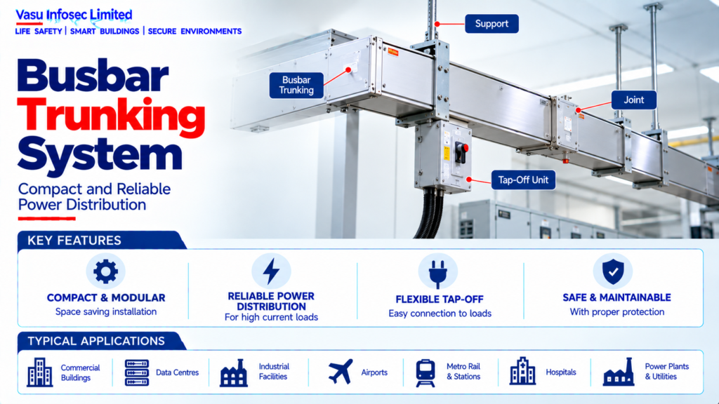
A Busbar Trunking System (BBT / Busway) is a prefabricated electrical distribution system using insulated busbars enclosed within a protective housing. It provides a compact, modular and maintainable alternative to conventional parallel power cables for distribution between transformers, switchboards, panels and major loads.
2. Complete Busbar Trunking Architecture
Transformer / DG / Main Switchboard → Busbar Trunking → Tap-Off Units → Distribution Boards / MCC / Loads
Busbar System → Conductors → Insulation → Enclosure → Joint Assemblies → End Feed / End Cap
Supporting Systems → PE / Earth Continuity → Tap-Off Protection → Hangers / Supports → Monitoring, where applicable
3. Busbar Trunking Types
Busbar systems may be selected as feeder busways, distribution busways or other manufacturer-defined arrangements. The construction may use different conductor materials and insulation systems according to current rating and project requirements.
4. Conductor Arrangement
The busbar assembly contains phase conductors and, where required, neutral and protective-earth conductors. Conductor configuration should match the electrical system, load characteristics and approved distribution philosophy.
5. Current Rating
Busbar rating should be selected based on the design current, ambient conditions, installation arrangement, enclosure characteristics, temperature rise and required future capacity. The selected rating should exceed the calculated operating demand with an appropriate engineering margin.
6. Short-Circuit Withstand
The busbar system must withstand the prospective short-circuit current for the specified duration and coordinate with upstream protective devices. Short-time and peak withstand ratings should be verified against the system fault level.
7. Voltage Rating
The busbar trunking voltage rating must be compatible with the electrical distribution system. Insulation level and dielectric performance should meet the approved equipment requirements.
8. Busbar Conductors
Conductors may be manufactured from copper or aluminium. Selection should consider conductivity, current rating, losses, weight, jointing arrangement, thermal performance and project specifications.
9. Insulation System
The insulation arrangement separates live conductors from each other and the enclosure. The selected insulation system should provide the required dielectric strength, temperature performance and environmental suitability.
10. Enclosure
The enclosure provides mechanical protection and may also form part of the protective-earthing path depending on the system design. Enclosure construction and ingress protection should suit the installation environment.
11. Joint Assembly
Busbar sections are connected using dedicated joint assemblies. Joints should provide reliable electrical contact, mechanical integrity and appropriate insulation. Joint torque and installation procedures should follow the manufacturer requirements.
12. Tap-Off Units
Tap-off units provide connection points for downstream loads along the busbar route. Each tap-off should have appropriate switching and protection and should be compatible with the busbar system.
13. Tap-Off Protection
Tap-off protection may use MCCBs, fuses or other approved devices. The protection rating should be coordinated with the downstream cable / equipment and the busbar system.
14. Plug-In Distribution
Distribution busways may provide multiple tap-off points along the route, allowing flexible connection of downstream loads. The arrangement should maintain required safety and load-distribution limits.
15. Feeder Busbar
Feeder busways are generally used for higher-current distribution between major electrical equipment such as transformers and main switchboards. The route and rating should be established from the electrical distribution design.
16. Neutral Conductor
The neutral arrangement should be selected according to the load characteristics. Facilities with significant nonlinear loads should assess neutral current and harmonic effects when determining neutral conductor requirements.
17. Protective Earth
The busbar system should provide an appropriate protective-earthing arrangement. Continuity across joints and tap-off connections should be maintained and verified.
18. Temperature Rise
Busbar temperature rise depends on current, enclosure design, ambient conditions, conductor material, installation orientation and ventilation. Manufacturer-rated temperature performance should be considered during selection.
19. Harmonic Considerations
Nonlinear loads can produce harmonic currents that affect conductor heating and neutral loading. The busbar design should consider the expected harmonic environment, especially in data centres and electronic-load facilities.
20. Installation Routing
Busbar routes should be coordinated with architectural, structural and MEP services. Clearances, access, expansion, bends, penetrations and equipment connection points should be established before installation.
21. Supports & Hangers
Busbar sections require appropriate supports and hangers at the manufacturer’s specified intervals and at changes in direction or other designated locations. Supports should account for mechanical and short-circuit forces.
22. Fire & Building Penetrations
Where busbar trunking passes through fire-rated walls or floors, approved fire-stopping and penetration arrangements should maintain the required fire separation. The installation should follow the approved building and fire-safety design.
23. Installation Requirements
Installation should verify:
- Correct busbar current rating
- Correct voltage rating
- Correct short-circuit withstand
- Correct conductor configuration
- Correct insulation system
- Correct enclosure / IP rating
- Correct joint assemblies
- Correct tap-off units
- Correct protective devices
- Correct earthing continuity
- Correct supports and clearances
- Proper identification and route coordination
24. Testing & Commissioning
Busbar commissioning should verify:
- Visual and mechanical inspection
- Joint integrity and torque
- Phase identification
- Insulation resistance where applicable
- Earth continuity
- Tap-off operation
- Protection operation
- Dielectric / withstand testing where specified
- Phase sequence
- Voltage verification
- Load-current and temperature observations where required
25. Maintenance
Maintenance should include inspection of joints, tap-off units, enclosure condition, supports, earthing continuity, signs of overheating and abnormal operating conditions. Thermal scanning may be used to identify high-resistance joints or overloaded sections.
26. Failure & Recovery
The system should be assessed for joint overheating, tap-off faults, insulation deterioration, mechanical damage, earth-continuity failure and overload. Faulted sections should be isolated and repaired according to the manufacturer’s procedure.
27. Design Change Control
Changes to load demand, transformer capacity, tap-off quantity, route, short-circuit level or downstream equipment should trigger a busbar capacity and coordination review.
28. Documentation
Busbar trunking documentation should include, as applicable:
- Busbar schedule
- Single-line diagram
- Busbar sizing calculation
- Route layout
- GA / installation drawings
- Joint details
- Tap-off schedule
- Short-circuit rating
- Protection coordination
- Supports / hanger details
- Fire-stopping details
- Testing and commissioning records
- As-built drawings
- O&M manual
29. Engineering Objective
The engineering objective is:
Determine Distribution Requirement → Calculate Design Current & Fault Level → Select Busbar Rating & Construction → Establish Route & Tap-Off Arrangement → Verify Temperature Rise & Short-Circuit Withstand → Design Supports, Earthing & Penetrations → Coordinate Protection → Test & Commission → Establish Safe, Flexible & Maintainable Electrical Distribution
Frequently Asked Questions
What determines busbar rating?
Design current, ambient conditions, installation arrangement, enclosure characteristics, temperature rise and future capacity.
Why is short-circuit withstand important?
The busbar must withstand prospective short-circuit current for the specified duration and coordinate with upstream protection.
What about fire-rated penetrations?
Approved fire-stopping and penetration arrangements should maintain required fire separation.
SEO & Publishing Details
| Field | Suggested website content |
| SEO title | Busbar Trunking System | Electrical Engineering Guide |
| Meta description | Learn about busbar trunking system, including architecture, design considerations, installation, testing, maintenance and documentation. |
| Primary keyword | busbar trunking system |
| Secondary keywords | busbar trunking system architecture, busbar trunking system design, busbar trunking system testing, electrical and power systems |
| Suggested URL slug | busbar-trunking-system |
| Suggested image alt text | Illustration of busbar trunking system architecture and main components |