
Article
Cable Sizing & Voltage Drop
Oct 2026
Direct Answer
Cable sizing selects a cable with adequate current-carrying capacity, insulation rating, short-circuit withstand, mechanical suitability and acceptable voltage drop for its installation. The design must coordinate the cable with the load, protective device and installation conditions.
1. Engineering Overview
Cable sizing is the process of selecting an electrical cable with adequate current-carrying capacity, insulation rating, short-circuit withstand, mechanical suitability and acceptable voltage drop for the intended installation. Proper sizing coordinates the cable with the load, protective device, installation method and environmental conditions.
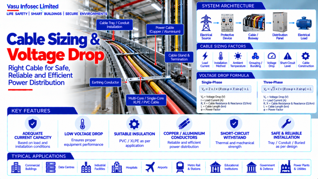
2. Complete Cable Sizing Architecture
Electrical Source → Protective Device → Cable / Busway → Distribution Panel / Equipment → Electrical Load
Cable Selection Inputs → Load Current → Installation Method → Ambient Conditions → Grouping → Voltage Drop → Short-Circuit Level → Cable Construction → Final Cable Size
Supporting Systems → Earthing Conductor → Cable Tray / Conduit → Glands / Terminations → Identification
3. Load Current Determination
Cable sizing begins with determining the design current of the connected load. The calculation should consider rated power, operating voltage, phase arrangement, power factor, efficiency where applicable and the approved demand / diversity assumptions.
4. Current-Carrying Capacity
The cable’s ampacity must be adequate for the design current under the actual installation conditions. Manufacturer or applicable standard tables should be used together with correction / derating factors.
5. Cable Conductor Material
Copper and aluminium conductors are commonly used. Selection should consider conductivity, installation characteristics, termination compatibility, weight, cost, mechanical requirements and project specifications.
6. Cable Insulation
Cable insulation should be selected according to system voltage, operating temperature, installation environment, fire performance requirements and applicable project specifications. Common insulation materials include PVC and XLPE for power applications.
7. Cable Construction
Cable construction may be single-core or multicore depending on voltage, current, installation arrangement and project requirements. Armour may be provided where mechanical protection or earthing requirements call for it.
8. Installation Method
Ampacity depends significantly on whether cables are installed in trays, conduits, ducts, trenches, buried directly or by another approved method. The selected installation method must be reflected in the sizing calculation.
9. Ambient Temperature Derating
Cable ampacity is affected by ambient temperature. Correction factors should be applied when the installation temperature differs from the reference conditions used in the cable ampacity tables.
10. Grouping / Bundling Derating
When multiple loaded circuits are installed close together, heat dissipation is reduced. Grouping factors should therefore be applied according to the installation arrangement and applicable cable data.
11. Soil / Ground Conditions
For buried cables, soil thermal resistivity, burial depth, soil temperature and grouping can affect cable ampacity. These parameters should be considered where underground installation is used.
12. Voltage Drop
Voltage drop is the reduction in voltage between the source and the load caused by the impedance of the cable. Excessive voltage drop can affect equipment performance, motor starting and system efficiency.
13. Voltage Drop Assessment
Voltage drop should be checked for the applicable operating condition and compared with the project / design limit. Both steady-state and significant motor-starting conditions should be assessed where relevant.
14. Cable Impedance
Cable resistance and reactance contribute to voltage drop. The calculation should use the appropriate conductor characteristics, installation arrangement, operating temperature and power factor.
15. Single-Phase Voltage Drop
For single-phase circuits, voltage-drop calculations should account for the complete current path, including outgoing and return conductors, using the appropriate cable impedance and circuit length.
16. Three-Phase Voltage Drop
For balanced three-phase circuits, voltage drop is calculated using the applicable three-phase relationship between current, cable impedance, circuit length and power factor.
17. Motor Circuit Sizing
Motor circuits should consider full-load current, starting current, starting method, acceleration characteristics, voltage drop during starting and protective-device coordination.
18. Lighting & Small Power Circuits
Lighting and small-power circuits should be sized for the design load, permissible voltage drop, installation method and protective-device rating. Circuit length and conductor temperature should be considered.
19. Short-Circuit Withstand
The cable must withstand the thermal and mechanical effects of prospective short-circuit current for the required fault-clearing time. Cable short-circuit withstand should be coordinated with protective-device operation.
20. Protective Device Coordination
The protective device should protect the cable against overload and short circuit while allowing normal operating current and expected starting conditions. Cable ampacity and breaker rating must be coordinated.
21. Neutral Conductor
Neutral conductor sizing should consider the expected neutral current, phase imbalance and harmonic currents. In installations with significant nonlinear loads, harmonic effects should be specifically assessed.
22. Earthing / Protective Conductor
Protective conductors should be sized and installed according to the approved earthing and fault-protection design. The arrangement must provide a suitable fault-current path for protective-device operation.
23. Cable Tray & Support
Cable trays, ladders and supports should be selected for the quantity, weight, heat dissipation and routing requirements of the cables. Separation of power, control and communication cables should follow the approved design.
24. Cable Termination
Cable glands, lugs, terminations and connection hardware should be compatible with the cable size, conductor material, insulation and equipment terminals. Termination torque should follow manufacturer requirements.
25. Cable Sizing Workflow
Typical workflow:
Determine Load → Calculate Design Current → Select Conductor Material & Insulation → Select Installation Method → Apply Ampacity Derating → Select Preliminary Cable Size → Check Voltage Drop → Check Short-Circuit Withstand → Coordinate Protective Device → Verify Terminations → Finalise Cable Size.
26. Installation Requirements
Installation should verify:
- Correct cable type
- Correct conductor size
- Correct insulation rating
- Correct number of cores
- Correct installation method
- Correct grouping / derating
- Correct voltage-drop compliance
- Correct short-circuit rating
- Correct protective-device coordination
- Correct earthing conductor
- Correct glands and lugs
- Proper cable routing and identification
27. Testing & Commissioning
Cable commissioning should verify:
- Visual inspection
- Cable identification
- Continuity
- Insulation resistance
- Phase identification
- Termination condition
- Earth continuity
- High-voltage / withstand testing where applicable
- Voltage measurement under load
- Voltage-drop verification where required
28. Maintenance
Maintenance should include inspection of cable terminations, signs of overheating, mechanical damage, insulation deterioration, tray supports, glands, earthing connections and abnormal loading. Thermographic inspection may be used where appropriate.
29. Failure & Recovery
Cable systems should be assessed for overload, short circuit, insulation failure, loose termination, mechanical damage and excessive voltage drop. Faulted circuits should be isolated and repaired under controlled procedures.
30. Design Change Control
Changes to load rating, cable route, installation method, ambient conditions, grouping, protective devices or source voltage should trigger a cable sizing and voltage-drop review.
31. Documentation
Cable sizing documentation should include, as applicable:
- Cable schedule
- Load schedule
- Cable sizing calculation
- Current-carrying capacity calculation
- Derating factors
- Voltage-drop calculation
- Short-circuit withstand calculation
- Protective-device coordination
- Cable tray / routing drawings
- Gland / termination schedule
- Testing and commissioning records
- As-built drawings
- O&M manual
32. Engineering Objective
The engineering objective is:
Determine Design Current → Select Cable Construction → Assess Installation & Derating → Select Preliminary Size → Verify Ampacity → Verify Voltage Drop → Verify Short-Circuit Withstand → Coordinate Protection & Earthing → Verify Terminations → Test & Commission → Establish Safe, Efficient & Reliable Cable Distribution
Frequently Asked Questions
What affects cable sizing?
Design current, ampacity, installation method, ambient temperature, grouping, soil conditions where buried, voltage drop, short-circuit withstand and protection coordination.
Why check voltage drop?
Excessive voltage drop can affect equipment performance, motor starting and system efficiency.
Why are derating factors applied?
Actual installation conditions can differ from reference conditions in cable ampacity tables.
SEO & Publishing Details
| Field | Suggested website content |
| SEO title | Cable Sizing & Voltage Drop | Electrical Engineering Guide |
| Meta description | Learn about cable sizing & voltage drop, including architecture, design considerations, installation, testing, maintenance and documentation. |
| Primary keyword | cable sizing & voltage drop |
| Secondary keywords | cable sizing & voltage drop architecture, cable sizing & voltage drop design, cable sizing & voltage drop testing, electrical and power systems |
| Suggested URL slug | cable-sizing-voltage-drop |
| Suggested image alt text | Illustration of cable sizing & voltage drop architecture and main components |