
Article
Cylinder Manifold & Valve Arrangement
Oct 2026
Direct Answer
The cylinder manifold and valve arrangement connects the gas suppression cylinder bank to the main distribution piping. It must be compatible with the selected agent, cylinder and storage pressure, approved actuation sequence, pressure supervision and manufacturer design, with manifold sizing and connections verified against the approved flow calculation.
1. Engineering Overview
The cylinder manifold and valve arrangement forms the controlled connection between the gas suppression cylinder bank and the main distribution piping network. The arrangement should provide reliable agent discharge, controlled flow, appropriate isolation, pressure supervision and compatibility with the approved cylinder bank and releasing system.
2. Basic Manifold & Valve Architecture
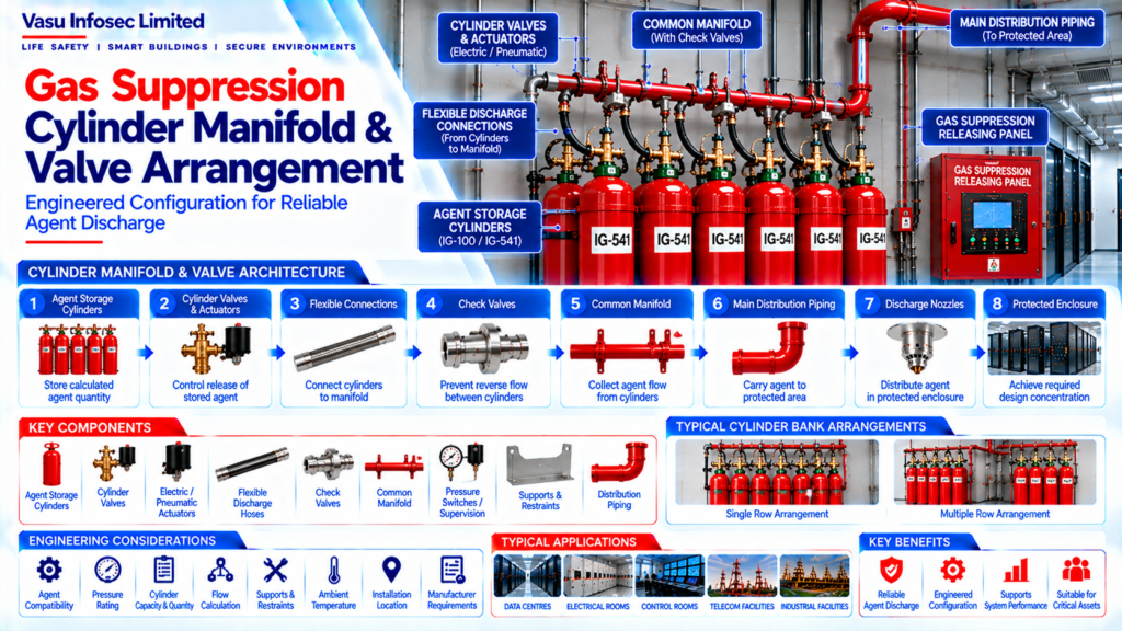
Storage Cylinders → Cylinder Valves → Actuation Mechanism → Flexible Discharge Connections → Check Valves → Common Manifold → Main Distribution Piping → Discharge Nozzles
3. Cylinder Valve Function
The cylinder valve controls the release of stored extinguishing agent from the cylinder. The valve should be compatible with the selected agent, cylinder, storage pressure, actuation arrangement and manufacturer-approved system configuration.
4. Valve Actuation
Automatic release may operate the cylinder valve through an approved electric, pneumatic or other manufacturer-specified actuation arrangement. The actuation sequence should be coordinated with the releasing control panel and Cause & Effect Matrix.
5. Flexible Discharge Connection
Flexible discharge connections provide the connection between individual cylinder valves and the manifold while accommodating the approved installation arrangement. They should be pressure-rated and compatible with the agent, valve and system configuration.
6. Check Valve Arrangement
Check valves may be installed in individual cylinder discharge paths to prevent reverse flow between cylinders and support controlled operation of the bank. Their arrangement should follow the selected manufacturer’s approved design.
7. Common Manifold
The common manifold receives agent flow from multiple cylinders and directs the combined flow into the distribution piping network. Manifold sizing, pressure rating and connection arrangement should be coordinated with the approved flow calculation.
8. Manifold Connection Arrangement
The manifold should provide secure, leak-resistant connections to all designated cylinder branches and the main distribution outlet. Connection sizes, thread / flange arrangements and pressure ratings should match the approved equipment.
9. Cylinder Bank Coordination
The manifold and valve arrangement should be coordinated with:
- Cylinder quantity
- Cylinder capacity
- Storage pressure
- Valve type
- Actuation method
- Flexible connections
- Check valves
- Main piping
- Flow calculation
10. Pressure Supervision
Where pressure supervision is provided, the arrangement should allow monitoring of the relevant cylinder or bank condition. Supervisory signals should be transmitted to the releasing control system according to the approved architecture.
11. Isolation & Maintenance
The system arrangement should support safe inspection and maintenance. Any isolation provisions should be controlled through the approved impairment procedure and should not compromise the required life-safety protection during normal operation.
12. Pipe & Manifold Support
Manifolds, valves and associated piping should be adequately supported to maintain alignment and mechanical stability. Supports should be installed according to approved manufacturer details and project requirements.
13. Flow & Hydraulic Coordination
The manifold and valve arrangement directly affects the flow characteristics of the suppression system. The final arrangement should therefore correspond with the approved hydraulic / flow calculation, cylinder configuration and nozzle network.
14. Installation Requirements
Installation should verify:
- Correct valve type
- Correct actuator
- Correct flexible connection
- Correct check valve direction
- Secure manifold connections
- Correct pipe alignment
- Adequate supports
- Correct pressure supervision
- Accessibility for maintenance
15. Testing & Commissioning
Testing should verify the complete manifold and valve arrangement.
Checks may include:
- Visual inspection
- Valve identification
- Actuator verification
- Flexible connection inspection
- Check valve verification
- Manifold connection inspection
- Pressure supervision
- Release sequence simulation
- Leak / integrity checks as applicable
16. Common Engineering Considerations
Engineering review should verify:
- Agent compatibility
- Pressure rating
- Valve compatibility
- Actuation arrangement
- Manifold capacity
- Check valve configuration
- Flexible hose suitability
- Flow calculation
- Supports and restraints
- Maintenance access
17. Documentation
Manifold and valve documentation should include, as applicable:
- Valve datasheets
- Actuator datasheets
- Manifold datasheet
- Flexible hose details
- Check valve details
- Cylinder schedule
- Manifold arrangement drawing
- Piping / flow calculation
- Installation details
- Testing records
- Commissioning records
- As-built documentation
18. Engineering Objective
The engineering objective is:
Correct Cylinder Valve Selection → Reliable Actuation → Controlled Flexible Connections → Effective Check Valve Arrangement → Adequate Manifold Capacity → Stable Pressure & Flow → Secure Installation → Verified Supervision → Complete Testing → Reliable Gas Suppression Discharge Performance
Frequently Asked Questions
What is the purpose of the common manifold?
It receives agent flow from multiple cylinders and directs the combined flow into the main distribution piping network.
Why must valve and actuator compatibility be checked?
The valve must suit the selected agent, cylinder and storage pressure, while the actuation arrangement must match the approved release sequence and manufacturer system configuration.
What is the role of check valves in the cylinder bank?
Where included, check valves help prevent reverse flow between cylinder discharge paths. Their configuration should follow the selected manufacturer’s approved design.
What should be checked during installation?
Verify valve and actuator types, flexible connections, check-valve direction, manifold connections, pipe alignment, supports, pressure supervision and maintenance access.
What documents should be retained?
As applicable, retain valve and actuator datasheets, manifold and hose details, check-valve details, cylinder schedule, arrangement drawings, flow calculations, installation details, testing and commissioning records, and as-built documentation.
SEO & Publication Metadata
SEO title: Gas Suppression Cylinder Manifold and Valve Arrangement | Vasu Infosec
Meta description: Understand gas suppression cylinder manifold and valve arrangements, including actuators, flexible connections, check valves, pressure supervision, flow coordination and commissioning.
Suggested URL slug: gas-suppression-cylinder-manifold-valve-arrangement
Primary keywords: gas suppression manifold, cylinder valve arrangement, gas suppression check valve, cylinder actuator, gas suppression manifold flow calculation
Suggested internal links: Gas Suppression Cylinder Bank Architecture; Gas Suppression Cylinder Selection; Gas Suppression Agent Quantity Calculation; Gas Suppression System Design Workflow.