
Article
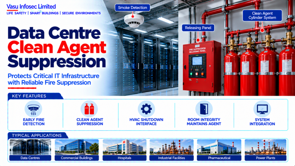
Data Centre Clean Agent Suppression
Oct 2026
Direct Answer
A Data Centre Clean Agent Suppression System is designed to control or extinguish fire in critical IT and electrical spaces while minimising damage to sensitive electronic equipment. The architecture integrates fire detection, clean-agent storage, releasing controls, distribution pipework, discharge nozzles, room integrity, HVAC control, alarm notification and post-discharge monitoring.
1. Engineering Overview
A Data Centre Clean Agent Suppression System is designed to control or extinguish fire in critical IT and electrical spaces while minimising damage to sensitive electronic equipment. The architecture integrates fire detection, clean-agent storage, releasing controls, distribution pipework, discharge nozzles, room integrity, HVAC control, alarm notification and post-discharge monitoring.
2. Complete Clean Agent Architecture
Early Warning / Smoke Detection → Fire Alarm / Releasing Panel → Pre-Discharge Alarm → HVAC / Damper Control → Clean Agent Release → Cylinder / Bank → Manifold / Pipe Network → Discharge Nozzles → Protected Room → Hold Time / Post-Discharge Monitoring
Supporting Systems → Manual Release → Abort Switch → Pressure Relief → Room Integrity → BMS / IBMS → CCTV → Access Control → Emergency Power → Control Room
3. Suppression Philosophy
The suppression philosophy should establish protected spaces, agent selection, design concentration, discharge time, cylinder arrangement, releasing logic, warning sequence, HVAC shutdown, room integrity, pressure relief, manual release, abort operation and post-discharge procedures.
4. Protected Areas
Typical protected areas may include data halls, server rooms, network rooms, UPS rooms, electrical rooms and other critical equipment spaces identified by the approved fire-risk assessment.
5. Clean Agent Selection
Agent selection should consider fire type, required extinguishing concentration, occupied-space requirements, environmental considerations, equipment compatibility, storage arrangement and applicable project requirements.
6. Design Concentration
The required design concentration should be established from the selected agent, fire hazard and approved system design. Concentration calculations should consider room volume, temperature, altitude where applicable and the required safety margin.
7. Agent Quantity Calculation
Agent quantity should be determined from the approved calculation methodology and protected-room conditions. The calculation should account for enclosure volume, design concentration, environmental parameters and agent storage characteristics.
8. Cylinder Storage
Clean-agent cylinders should be located in an approved arrangement with suitable access, identification, protection and environmental conditions. Cylinder quantity and capacity should satisfy the approved system calculation.
9. Cylinder Manifold
Where multiple cylinders are used, a manifold arrangement may provide common distribution to the protected zone. Manifold sizing, check arrangements and cylinder sequencing should be compatible with the approved discharge design.
10. Distribution Pipework
Pipework should be designed to distribute the agent within the required discharge time and achieve the approved nozzle flow distribution. Pipe sizing, routing, fittings and supports should follow the approved hydraulic calculation.
11. Discharge Nozzles
Nozzles should be positioned to provide the required agent distribution throughout the protected enclosure. Nozzle selection, orifice sizing and orientation should be based on the approved hydraulic / flow calculation.
12. Detection Interface
Smoke detection should provide the initiating signal for the releasing sequence. Where aspirating detection is used, progressive alarm levels may be integrated with the suppression releasing logic.
13. Releasing Panel
The releasing panel should supervise detection inputs, release circuits, abort / manual controls, actuator circuits, pressure switches and other designated system functions and should execute the approved release sequence.
14. Pre-Discharge Alarm
A pre-discharge warning should provide occupants and operators with appropriate notification before agent release. Audible and visual notification should be coordinated with the protected-room operating procedure.
15. HVAC Shutdown
HVAC equipment serving the protected enclosure should be shut down, isolated or otherwise controlled before agent discharge where required. The objective is to prevent agent loss and maintain the required extinguishing concentration.
16. Dampers & Openings
Doors, dampers and other openings should be controlled as necessary to maintain enclosure integrity during and after discharge. The response should be defined in the approved cause-and-effect matrix.
17. Manual Release
A manual release facility should be provided where required. It should be clearly identified, accessible and protected against inadvertent operation while remaining available for emergency use.
18. Abort Function
An abort function may be provided to delay or prevent discharge while an alarm is being investigated, subject to the approved suppression philosophy. Abort operation, timing and priority should be clearly defined.
19. Pressure Relief
Clean-agent discharge can create pressure changes within a protected enclosure. Pressure-relief provisions should be assessed and sized according to the approved room-integrity and pressure analysis.
20. Room Integrity
The protected enclosure should maintain sufficient integrity to retain the agent for the required hold period. Walls, ceilings, floors, doors, dampers, cable penetrations and other openings should be assessed.
21. Room Integrity Testing
Integrity testing should verify leakage characteristics and confirm that the enclosure can maintain the required agent concentration for the specified period. Deficiencies should be rectified and retested.
22. Fire Alarm Interface
Clean-agent alarms, pre-discharge status, discharge status, system fault and supervisory conditions should be integrated with the fire alarm system as defined by the approved interface philosophy.
23. BMS / IBMS Interface
Clean-agent system status, alarms and faults may be monitored through BMS / IBMS. Fire-system control logic should remain under the approved releasing-system architecture.
24. CCTV Interface
CCTV may provide visual verification of protected-room conditions and alarm events. Relevant cameras may be automatically displayed at the control room where integrated.
25. Access Control Interface
Access control should coordinate with emergency egress and responder access. Doors required for life safety should not be prevented from operating by normal access-control restrictions.
26. Emergency Power
Releasing panels, detection systems, notification devices and other critical suppression controls should have reliable emergency / standby power with appropriate battery autonomy.
27. Installation Requirements
Installation should verify:
- Correct protected-room identification • Correct agent selection • Correct agent quantity • Correct cylinder capacity and arrangement • Correct manifold configuration • Correct pipework installation • Correct nozzle location and orientation • Correct releasing panel • Correct detection interface • Correct HVAC shutdown • Correct manual release / abort • Correct pressure-relief provisions • Correct room-integrity provisions • Correct alarm / BMS / CCTV interfaces • Correct emergency power
28. Testing & Commissioning
Commissioning should verify:
- Cylinder and valve condition • Pipework integrity • Nozzle installation • Detection operation • Releasing panel operation • Pre-discharge alarm • HVAC shutdown • Damper / door response • Manual release • Abort function • Pressure-relief arrangement • Room integrity • Alarm / BMS interface • Emergency power • Fault monitoring
29. Functional Release Testing
Functional testing should verify the releasing sequence using approved non-discharge or controlled test methods where practical. Any live discharge testing should follow the approved procedure, safety controls and client requirements.
30. Integrated Fire Scenario Testing
Representative data-centre fire scenarios should verify the complete sequence from early detection through alarm escalation, pre-discharge warning, HVAC control, release logic, agent discharge where approved, post-discharge monitoring and control-room response.
31. Maintenance
Maintenance should include cylinder inspection, pressure / weight checks as applicable, valve and actuator inspection, pipework and nozzle inspection, releasing-panel testing, detection testing, room-integrity review and HVAC interface testing.
32. Impairment Management
Any impairment of clean-agent suppression, detection, room integrity or releasing controls should be formally controlled with compensatory measures, responsible persons, notifications, duration and restoration requirements.
33. Failure & Recovery
The system should be assessed for cylinder pressure loss, actuator failure, releasing-panel fault, detector failure, pipework obstruction, room-integrity degradation, HVAC-control failure and power loss. Recovery procedures should prioritise critical IT protection.
34. Design Change Control
Changes to protected-room volume, partitions, doors, cable routes, raised floors, ceiling voids, HVAC systems or equipment layouts should trigger a review of agent quantity, nozzle distribution, room integrity and releasing logic.
35. Documentation
Clean-agent suppression documentation should include, as applicable:
- Suppression philosophy • Protected-zone drawings • Agent selection basis • Design concentration calculation • Agent quantity calculation • Cylinder schedule • Manifold details • Pipe-network calculation • Nozzle schedule • Releasing-panel architecture • Cause-and-effect matrix • HVAC interface details • Room-integrity calculation / test report • Pressure-relief calculation • Manual release / abort details • BMS / IBMS interface • CCTV / access-control interface • Emergency-power calculation • Testing and commissioning records • Maintenance schedule • Impairment procedures • As-built drawings • O&M manual
36. Engineering Objective
The engineering objective is:
Assess Protected Data-Centre Risk → Select Suitable Clean Agent → Establish Design Concentration & Agent Quantity → Design Cylinders, Manifold, Pipework & Nozzles → Integrate Detection & Releasing Logic → Control HVAC & Openings → Verify Room Integrity & Pressure Relief → Integrate Fire Alarm, BMS / IBMS, CCTV & Access Control → Provide Emergency Power → Test Release Sequence & Integrated Fire Scenarios → Maintain Reliable Clean-Agent Protection
Frequently Asked Questions
What should be considered for suppression philosophy?
The suppression philosophy should establish protected spaces, agent selection, design concentration, discharge time, cylinder arrangement, releasing logic, warning sequence, HVAC shutdown, room integrity, pressure relief, manual release, abort operation and post-discharge procedures.
What should be considered for clean agent selection?
Agent selection should consider fire type, required extinguishing concentration, occupied-space requirements, environmental considerations, equipment compatibility, storage arrangement and applicable project requirements.
What should be considered for detection interface?
Smoke detection should provide the initiating signal for the releasing sequence. Where aspirating detection is used, progressive alarm levels may be integrated with the suppression releasing logic.
What should be considered for room integrity?
The protected enclosure should maintain sufficient integrity to retain the agent for the required hold period. Walls, ceilings, floors, doors, dampers, cable penetrations and other openings should be assessed.
What should be considered for room integrity testing?
Integrity testing should verify leakage characteristics and confirm that the enclosure can maintain the required agent concentration for the specified period. Deficiencies should be rectified and retested.
SEO & Publishing Details
| SEO title | Data Centre Clean Agent Suppression | Vasu Infosec Limited |
| Meta description | A Data Centre Clean Agent Suppression System is designed to control or extinguish fire in critical IT and electrical spaces while minimising damage to… |
| Primary keyword | data centre clean agent suppression |
| Secondary keywords | data centre, clean agent, data centre, clean agent, room integrity, hvac |
| Suggested URL slug | data-centre-clean-agent-suppression |
| Suggested image alt text | Technical architecture illustration for data centre clean agent suppression in data-centre engineering. |