
Article
Data Centre Room Integrity
Oct 2026
Direct Answer
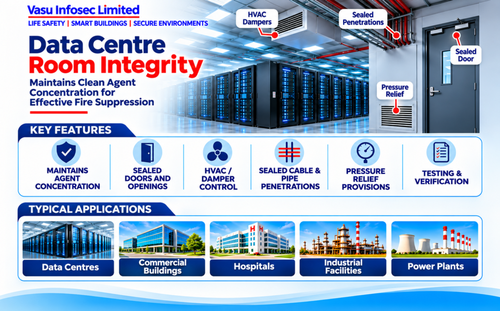
Data Centre Room Integrity is the engineering assessment and verification of a protected enclosure’s ability to retain the required concentration of clean agent for the specified hold period. The integrity of walls, floors, ceilings, doors, dampers, cable penetrations, pipe penetrations, ventilation openings and other leakage paths is critical to clean-agent system performance.
1. Engineering Overview
Data Centre Room Integrity is the engineering assessment and verification of a protected enclosure’s ability to retain the required concentration of clean agent for the specified hold period. The integrity of walls, floors, ceilings, doors, dampers, cable penetrations, pipe penetrations, ventilation openings and other leakage paths is critical to clean-agent system performance.
2. Complete Room Integrity Architecture
Protected Room → Enclosure Boundaries → Doors / Glazing → Cable & Pipe Penetrations → HVAC Openings / Dampers → Pressure Relief → Clean Agent Discharge → Agent Retention → Hold Period
Supporting Systems → Room Integrity Calculation → Enclosure Inspection → Door / Damper Verification → Penetration Sealing → Integrity Test → Clean Agent System → Fire Alarm → HVAC → BMS / IBMS → Control Room
3. Room Integrity Philosophy
The room-integrity philosophy should establish the protected volume, enclosure construction, leakage assessment, agent-retention requirement, hold period, pressure effects, pressure-relief provisions, door and damper requirements, penetration sealing and testing methodology.
4. Protected Room Identification
All rooms intended for clean-agent protection should be clearly identified and their boundaries established. Protected volumes should include relevant ceiling voids, raised-floor voids and other connected spaces where they form part of the suppression enclosure.
5. Protected Volume Assessment
The protected volume should be determined from the actual enclosure dimensions and approved design information. Permanent structural elements and relevant void spaces should be considered consistently with the clean-agent calculation.
6. Enclosure Boundaries
Walls, floors and ceilings forming the protected enclosure should provide suitable construction and continuity to minimise agent leakage. Joints, interfaces and service openings should be reviewed during installation inspection.
7. Doors
Doors serving protected rooms should provide appropriate sealing and closing performance. Door gaps, frames, thresholds, closers and door hardware should be inspected as part of the integrity assessment.
8. Glazing & Openings
Glazing, access panels, louvers and other openings within the protected enclosure should be assessed for leakage. Any openings that could materially affect agent retention should be addressed.
9. Cable Penetrations
Cable trays, conduits and individual cables passing through enclosure boundaries should be sealed using suitable penetration systems. Seals should maintain the required enclosure integrity and should be inspected after installation.
10. Pipe Penetrations
Pipework passing through protected-room boundaries should be appropriately sealed. Penetration details should account for pipe material, movement, thermal conditions and the required fire / enclosure performance.
11. HVAC Openings
Supply and return-air openings can provide significant leakage paths during clean-agent discharge. HVAC openings should therefore be controlled through approved shutdown, isolation or damper arrangements.
12. Dampers
Dampers serving protected rooms should achieve the required closed condition during the suppression sequence. Damper type, actuator, fail position, sealing and status feedback should be coordinated with the fire system.
13. Pressure Relief
Clean-agent discharge may create positive or negative pressure within a protected room. Pressure-relief arrangements should be assessed and sized so that enclosure pressure remains within acceptable limits.
14. Room Integrity Calculation
The room-integrity design should establish the leakage characteristics required to maintain the clean-agent concentration for the specified hold period. Calculation assumptions should be consistent with the agent system design.
15. Hold Time
The required hold period should be established by the approved clean-agent design and fire strategy. The enclosure should retain sufficient agent concentration throughout this period to support extinguishment and prevent re-ignition.
16. Agent Concentration Relationship
Room integrity directly affects clean-agent concentration decay. Leakage paths should therefore be controlled so that the calculated and tested enclosure performance supports the required design concentration and hold time.
17. Integrity Testing Method
Room integrity should be verified using an approved enclosure-integrity test method. The test should identify leakage characteristics and provide an assessment of whether the enclosure can maintain the required agent concentration.
18. Door & Damper Functional Test
During commissioning, doors and dampers should be functionally tested to confirm correct closing, sealing, actuator operation, control response and status feedback.
19. Pressure Monitoring
Where required, pressure during clean-agent discharge should be assessed to confirm that enclosure construction and pressure-relief provisions remain within acceptable limits.
20. Fire Alarm Interface
Room-integrity status should be considered in the overall clean-agent fire-protection sequence. Fire alarm and releasing controls should coordinate detection, pre-discharge, HVAC shutdown and agent release.
21. Clean Agent Interface
Room integrity is a prerequisite for effective clean-agent suppression. Agent quantity and discharge calculations should be based on the actual protected enclosure and its verified leakage characteristics.
22. HVAC Integration
HVAC shutdown or isolation should occur according to the approved cause-and-effect sequence. Post-discharge ventilation should be controlled in accordance with the approved recovery procedure.
23. BMS / IBMS Interface
Relevant room status, HVAC condition, damper status and clean-agent alarms may be monitored through BMS / IBMS. Safety-critical release logic should remain under the approved fire-protection control system.
24. Environmental Considerations
Temperature, pressure, humidity and airflow conditions may affect room-integrity performance and clean-agent behaviour. Relevant environmental assumptions should be considered in design and testing.
25. Installation Requirements
Installation should verify:
- Correct protected-room boundaries • Correct protected volume • Continuous enclosure construction • Correct door sealing and closing • Correct glazing and opening treatment • Correct cable penetration seals • Correct pipe penetration seals • Correct HVAC isolation • Correct damper operation • Correct pressure-relief provisions • Correct room-integrity calculation • Correct integrity testing • Correct clean-agent interface • Proper identification and accessibility
26. Testing & Commissioning
Room-integrity commissioning should verify:
- Enclosure condition • Door operation and sealing • Damper operation • Penetration seals • HVAC shutdown / isolation • Pressure-relief arrangement • Room volume • Integrity-test results • Hold-time assessment • Clean-agent design assumptions • Fire alarm / releasing interface • BMS / IBMS status where provided
27. Integrity Test Procedure
The test should be conducted after completion of enclosure construction and sealing works. All identified leakage paths should be included in the assessment. Deficiencies should be rectified and the enclosure retested.
28. Defect Management
Defects such as excessive leakage, damaged seals, improperly closing doors, failed dampers or unsealed penetrations should be documented and corrected before final acceptance of the clean-agent system.
29. Maintenance
Room integrity should be periodically inspected for new penetrations, damaged seals, door modifications, partition changes, HVAC alterations and other changes that could affect agent retention.
30. Impairment Management
Any activity that compromises enclosure integrity should be treated as a suppression-system impairment. Appropriate compensatory measures should be established until the enclosure is restored and verified.
31. Failure & Recovery
The system should be assessed for door failure, damper failure, seal degradation, new cable penetrations, partition changes, HVAC leakage and pressure-relief problems. Recovery should include rectification and, where required, repeat integrity testing.
32. Design Change Control
Changes to room dimensions, partitions, raised floors, ceiling voids, cable routes, pipework, doors, HVAC systems or equipment layout should trigger a review of protected volume, leakage and clean-agent requirements.
33. Documentation
Data-centre room-integrity documentation should include, as applicable:
- Protected-room drawings • Enclosure boundary details • Protected-volume calculation • Room-integrity calculation • Leakage assessment • Door schedule • Damper schedule • Penetration-sealing details • Pressure-relief calculation • Clean-agent design concentration • Hold-time assessment • Integrity-test procedure • Integrity-test report • HVAC interface details • Cause-and-effect matrix • Defect / corrective-action records • Maintenance schedule • As-built drawings • O&M manual
34. Engineering Objective
The engineering objective is:
Define Protected Enclosure → Establish Protected Volume → Identify Leakage Paths → Seal Doors, Penetrations & Openings → Coordinate HVAC & Dampers → Assess Pressure Relief → Calculate Agent Retention & Hold Time → Conduct Room Integrity Testing → Rectify Deficiencies → Verify Clean-Agent Performance → Maintain Enclosure Integrity Throughout the Data-Centre Lifecycle
Frequently Asked Questions
What should be considered for room integrity philosophy?
The room-integrity philosophy should establish the protected volume, enclosure construction, leakage assessment, agent-retention requirement, hold period, pressure effects, pressure-relief provisions, door and damper requirements, penetration sealing and testing methodology.
What should be considered for room integrity calculation?
The room-integrity design should establish the leakage characteristics required to maintain the clean-agent concentration for the specified hold period. Calculation assumptions should be consistent with the agent system design.
What should be considered for integrity testing method?
Room integrity should be verified using an approved enclosure-integrity test method. The test should identify leakage characteristics and provide an assessment of whether the enclosure can maintain the required agent concentration.
What should be considered for fire alarm interface?
Room-integrity status should be considered in the overall clean-agent fire-protection sequence. Fire alarm and releasing controls should coordinate detection, pre-discharge, HVAC shutdown and agent release.
What should be considered for clean agent interface?
Room integrity is a prerequisite for effective clean-agent suppression. Agent quantity and discharge calculations should be based on the actual protected enclosure and its verified leakage characteristics.
SEO & Publishing Details
| SEO title | Data Centre Room Integrity | Vasu Infosec Limited |
| Meta description | Data Centre Room Integrity is the engineering assessment and verification of a protected enclosure’s ability to retain the required concentration of clean… |
| Primary keyword | data centre room integrity |
| Secondary keywords | data centre, room integrity, data centre, room integrity, clean agent |
| Suggested URL slug | data-centre-room-integrity |
| Suggested image alt text | Technical architecture illustration for data centre room integrity in data-centre engineering. |