
Article
DG Set Architecture
Oct 2026
Direct Answer
A Diesel Generator (DG) set provides standby or prime electrical power using an engine-driven alternator and associated fuel, cooling, exhaust, starting, control and protection systems. Capacity should be based on designated loads and operating conditions.
1. Engineering Overview
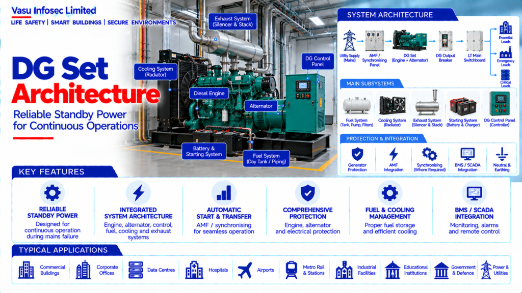
A Diesel Generator (DG) Set is a standby or prime electrical power source comprising a diesel engine, alternator, fuel system, cooling system, exhaust system, starting system, control panel and associated electrical protection. DG architecture is designed to provide reliable power to designated loads during utility failure or other approved operating conditions.
2. Complete DG Set Architecture
Diesel Engine → Alternator → DG Output Breaker → LT Main Switchboard / Synchronising Panel → Essential / Emergency Loads
Fuel System → Day Tank / Main Fuel Tank → Fuel Pump → Engine
Cooling System → Radiator / Cooling Circuit
Exhaust System → Exhaust Manifold → Silencer → Exhaust Stack
Starting System → Battery / Charger → Starter Motor
Control System → DG Controller → AMF / Synchronising / BMS / SCADA
Protection → Engine Protection + Alternator Protection + Breaker Protection
3. DG Set Rating
DG capacity is normally specified in kVA / MVA and should be selected based on the designated electrical load, starting characteristics, power factor, operating philosophy, altitude, ambient temperature, redundancy and future requirements.
4. Standby vs Prime Operation
Standby DG sets are generally intended to operate during utility outages, while prime-rated systems are designed for more extensive operating duty. The selected rating and operating class should match the project requirement and manufacturer specification.
5. DG Load Assessment
DG sizing should consider the loads intended to operate during utility failure. Motor starting currents, nonlinear loads, UPS systems, HVAC loads and other transient demands should be evaluated rather than relying only on steady-state connected load.
6. Load Sequencing
Where required, essential loads may be connected in a defined sequence after DG stabilisation. Load sequencing can reduce starting transients and prevent excessive generator voltage or frequency disturbance.
7. Engine Architecture
The diesel engine converts fuel energy into mechanical power to drive the alternator. Engine selection should consider rated output, speed, fuel consumption, cooling, emissions, altitude and ambient operating conditions.
8. Alternator Architecture
The alternator converts mechanical energy into electrical energy. Alternator selection should consider voltage, frequency, kVA rating, insulation class, temperature rise, short-circuit characteristics and transient performance.
9. Fuel System
The fuel system may include a bulk storage tank, day tank, transfer pump, filters, piping and level monitoring. Fuel capacity should be based on the required autonomy and approved operating conditions.
10. Cooling System
DG engines require a cooling system to control operating temperature. Radiator cooling or other approved arrangements should be selected according to engine rating, ambient conditions and installation configuration.
11. Exhaust System
The exhaust system conveys combustion gases safely outside the generator enclosure or plant area. Exhaust piping, silencer, flexible connection, supports, insulation and discharge location should be coordinated with the architectural and mechanical design.
12. Starting System
The starting system commonly includes batteries, battery charger and starter motor. Battery capacity and charger rating should support reliable starting under the specified environmental conditions.
13. DG Control Panel
The DG controller monitors engine and alternator parameters and manages starting, stopping, alarms, shutdowns and status indications. It may also communicate with AMF, synchronising and building monitoring systems.
14. AMF Integration
The Automatic Mains Failure system detects utility failure and initiates the approved DG start and source-transfer sequence. Utility restoration should initiate the approved return-to-normal sequence after the required stability period.
15. Synchronising System
Where multiple DG sets or utility paralleling are required, a synchronising system coordinates voltage, frequency and phase before connecting sources in parallel. Load sharing and source control should be defined in the approved operating philosophy.
16. DG Output Breaker
The DG output breaker connects the generator to the electrical distribution system. Its rating, interrupting capacity, protection and interlocking should be coordinated with the generator and downstream switchgear.
17. Generator Protection
Protection may include overcurrent, short circuit, earth fault, over / under voltage, over / under frequency, reverse power, phase sequence and other functions appropriate to the generator application.
18. Neutral & Earthing
Generator neutral grounding and equipment earthing should follow the approved electrical earthing philosophy. The arrangement must be coordinated with transformer neutral grounding, protection settings and source-transfer logic.
19. DG and UPS Integration
Where UPS systems supply critical loads, the DG must be capable of supporting the UPS input characteristics. Generator transient performance, harmonic loading and UPS compatibility should be evaluated.
20. Power Quality
DG operation should maintain acceptable voltage and frequency performance for connected loads. Nonlinear loads, UPS systems and large motors should be considered when evaluating alternator and generator performance.
21. Acoustic & Environmental Considerations
DG installations should address noise, vibration, heat rejection, ventilation, exhaust emissions, fuel handling and environmental conditions. Acoustic treatment and ventilation arrangements should be designed according to the project requirements.
22. Installation Requirements
Installation should verify:
- Correct DG capacity
- Correct voltage and frequency
- Correct engine / alternator configuration
- Correct fuel system
- Correct cooling arrangement
- Correct exhaust arrangement
- Correct battery and charger
- Correct output breaker
- Correct AMF / synchronising interface
- Correct protection settings
- Correct earthing
- Proper ventilation and access
23. Testing & Commissioning
DG commissioning should verify:
- Pre-start inspection
- Battery and charger operation
- Manual start / stop
- Automatic start
- Voltage and frequency
- Load acceptance
- Load transfer
- AMF operation
- Return-to-mains sequence
- Protection trips and alarms
- Emergency stop
- Fuel and cooling alarms
- Synchronising, where applicable
24. Maintenance
Maintenance should include engine inspection, oil and filter checks, cooling-system inspection, battery testing, fuel-system checks, exhaust inspection, alternator inspection, control-panel checks and periodic loaded testing.
25. Failure & Recovery
The system should be assessed for DG start failure, breaker failure, low fuel, high temperature, overspeed, electrical protection trip and control-system failure. Alternate-source and recovery procedures should be defined for critical loads.
26. Design Change Control
Changes to essential load, DG rating, number of DG sets, synchronising philosophy, AMF logic, fuel autonomy, UPS characteristics or distribution architecture should trigger a DG capacity and control review.
27. Documentation
DG documentation should include, as applicable:
- DG schedule
- Load calculation
- DG sizing calculation
- Manufacturer datasheet
- Single-line diagram
- AMF / synchronising logic
- Protection settings
- Fuel autonomy calculation
- Exhaust / ventilation details
- Battery / charger details
- Testing and commissioning records
- Maintenance schedule
- As-built drawings
- O&M manual
28. Engineering Objective
The engineering objective is:
Define Essential Load Requirement → Determine DG Capacity → Evaluate Starting & Transient Loads → Select Engine & Alternator → Design Fuel, Cooling & Exhaust Systems → Integrate AMF / Synchronising → Establish Protection & Earthing → Test Load Transfer & Recovery → Establish Reliable Emergency Power Generation
Frequently Asked Questions
What determines generator/AMF operation?
The approved operating philosophy defines load classification, start and restoration delays, generator availability, source transfer, interlocking and return-to-normal sequence.
What should be verified during commissioning?
The source lists automatic start, voltage/frequency availability, load transfer, return-to-mains, protection, interlocks and relevant alarms; the exact checks depend on the system.
Can mains and generator sources be connected simultaneously?
Only where the system is specifically designed for synchronised paralleling and includes appropriate synchronising, protection and interlocking.
SEO & Publishing Details
| Field | Suggested website content |
| SEO title | DG Set Architecture | Electrical Engineering Guide |
| Meta description | Understand dg set architecture, including system architecture, key components, design considerations, installation, testing, maintenance and documentation. |
| Primary keyword | dg set architecture |
| Secondary keywords | dg set architecture architecture, dg set architecture design, dg set architecture sizing, dg set architecture testing, electrical and power systems |
| Suggested URL slug | dg-set-architecture |
| Suggested image alt text | Illustration of dg set architecture architecture and main components |