
Article
Electrical Load Calculation
Oct 2026
Direct Answer
Electrical load calculation determines the connected, demand, diversified and expected maximum electrical load of a facility or distribution system. The results support sizing of transformers, DG sets, UPS systems, switchboards, cables and protective devices.
1. Engineering Overview
Electrical Load Calculation is the structured process of determining the connected, demand, diversified and maximum expected electrical load of a facility or distribution system. The results form the basis for sizing transformers, DG sets, UPS systems, switchboards, cables, protective devices and other electrical infrastructure.
2. Complete Load Calculation Architecture
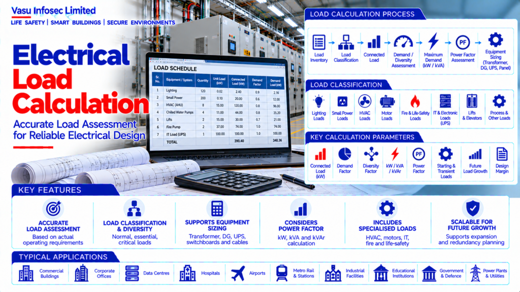
Load Inventory → Connected Load Schedule → Load Classification → Demand / Diversity Assessment → Maximum Demand → Power Factor Assessment → kW / kVA Calculation → Source & Equipment Sizing → Protection & Distribution Review → Future Load Assessment
3. Load Inventory
The calculation should begin with a complete inventory of electrical equipment and systems. Each load should be identified with its equipment description, quantity, rated capacity, operating voltage, phase, power factor and operating characteristics where available.
4. Connected Load
Connected load is the total rated electrical capacity of all equipment connected to a distribution system. It represents installed capacity and should not automatically be treated as the actual simultaneous operating demand.
5. Demand Load
Demand load represents the expected electrical requirement considering the operating characteristics of the connected loads. Demand factors should be established from the approved design criteria and actual facility operating philosophy.
6. Diversity Factor
Diversity accounts for the fact that individual loads may not reach their maximum demand at the same time. The selected diversity assumptions should be technically justified and appropriate for the load category.
7. Load Classification
Loads should be classified according to function and operational importance. Typical categories include lighting, small power, HVAC, pumps, fire and life-safety systems, lifts, IT loads, process equipment, UPS loads and other specialised systems.
8. Normal, Essential & Critical Loads
Facilities may segregate normal, essential, emergency and critical loads. Each category should have a defined source and distribution arrangement, particularly where DG or UPS systems are provided.
9. Single-Phase Load Calculation
For a single-phase load, apparent power may be determined from voltage and current, while active power depends on the applicable power factor. The calculation should use the equipment’s rated or measured parameters as appropriate.
10. Three-Phase Load Calculation
For a balanced three-phase system, apparent power may be determined using line voltage and line current. Active power is related to apparent power and power factor. The selected calculation basis should remain consistent throughout the load schedule.
11. kW, kVA & kVAr
Electrical load calculations should distinguish between active power (kW), apparent power (kVA) and reactive power (kVAr). This distinction is essential for transformer, DG, UPS and power-factor-correction sizing.
12. Motor Loads
Motor loads should account for rated running power, efficiency, power factor and starting characteristics. Large motors may require additional assessment for starting current and voltage drop.
13. HVAC Loads
HVAC loads may include chillers, pumps, AHUs, fans, cooling towers and other equipment. The operating sequence and diversity of HVAC equipment should be considered when determining maximum demand.
14. Lighting Loads
Lighting load calculations should consider installed fixture wattage, quantity, control strategy and operating schedule. Emergency lighting should be classified according to its designated power source.
15. Small Power Loads
Small power includes sockets, office equipment, local appliances and other general-use loads. Appropriate demand assumptions should be applied based on the intended facility use.
16. IT & Electronic Loads
IT and electronic loads may have high continuity requirements and nonlinear current characteristics. Critical IT loads should be separately identified for UPS and emergency-power sizing.
17. Fire & Life-Safety Loads
Fire alarm, fire pumps, smoke control, emergency lighting and other life-safety systems should be separately identified and assessed according to the approved emergency-power philosophy.
18. DG Load Calculation
DG sizing should be based on the designated loads that must operate during utility failure. Starting loads, sequential loading, motor characteristics and power-quality requirements should be considered.
19. UPS Load Calculation
UPS sizing should be based on the actual critical-load profile, including present load, expected expansion, power factor, nonlinear characteristics and required redundancy. Transient or inrush loads should be assessed where relevant.
20. Transformer Load Calculation
Transformer sizing should use the calculated maximum demand in kVA together with the approved design margin, future expansion and redundancy requirements. Transformer loading should be checked for normal and contingency conditions.
21. Load Schedule Structure
A typical load schedule may include:
- Load identification
- Quantity
- Unit rating
- Connected load
- Demand factor
- Diversity factor, where applied
- Calculated demand
- Power factor
- Calculated kVA
- Source
- Feeder / panel reference
- Essential / critical classification
22. Demand Factor Application
Demand factor is generally applied to a group of connected loads to estimate the expected maximum demand. The factor should be based on approved design criteria, manufacturer information or documented operational assumptions.
23. Diversity Assessment
Diversity should be applied carefully and should not be used to artificially reduce equipment capacity. Load categories with simultaneous operation should be assessed conservatively where operational data is unavailable.
24. Future Expansion
The calculation should identify justified future load requirements. Expansion allowances should be documented separately so that installed capacity and future capacity are clearly distinguishable.
25. Load Growth
Long-term load growth may result from additional equipment, increased occupancy, IT expansion, process changes or facility modifications. The selected growth allowance should reflect the expected development of the facility.
26. Load Balancing
Single-phase loads should be distributed appropriately across three-phase systems to reduce phase imbalance. Phase loading should be reviewed at distribution-board and main-panel levels.
27. Maximum Demand Calculation
Typical workflow:
List Connected Loads → Classify Loads → Determine Unit & Total Connected Load → Apply Demand / Diversity → Determine Maximum Demand → Apply Power Factor → Convert to kVA → Assess Source & Equipment Capacity → Check Future Growth & Redundancy.
28. Installation / Design Requirements
Load calculation should verify:
- Complete load inventory
- Correct equipment ratings
- Correct quantities
- Correct load classification
- Correct demand factors
- Correct diversity assumptions
- Correct power factors
- Correct source allocation
- Correct phase distribution
- Correct critical-load classification
- Correct future-growth allowance
- Consistency with single-line diagrams
29. Testing & Verification
After installation, calculated assumptions should be compared with measured operating data where practical. Electrical measurements can be used to validate loading, phase balance, power factor and actual demand.
30. Maintenance & Periodic Review
Load schedules should be reviewed when significant equipment is added, removed or replaced. Periodic energy and demand data can help identify changes in actual operating conditions and support future capacity planning.
31. Design Change Control
Changes to equipment quantity, ratings, operating schedules, HVAC systems, IT loads, UPS systems, DG capacity or process requirements should trigger a review of the electrical load calculation.
32. Documentation
Electrical load-calculation documentation should include, as applicable:
- Load schedule
- Connected-load calculation
- Demand calculation
- Diversity assumptions
- Power-factor assumptions
- Maximum-demand calculation
- Transformer sizing basis
- DG sizing basis
- UPS sizing basis
- Panel / feeder allocation
- Phase-balancing assessment
- Future-load allowance
- Supporting manufacturer data
- Approved single-line diagram
33. Engineering Objective
The engineering objective is:
Identify All Loads → Classify Normal / Essential / Critical Loads → Determine Connected Load → Apply Justified Demand & Diversity → Calculate Maximum Demand → Determine kW / kVA Requirement → Size Transformer / DG / UPS / Panels → Verify Phase Balance & Future Growth → Validate Against Operating Data → Establish Accurate & Defensible Electrical Capacity Planning
Frequently Asked Questions
What is the difference between connected load and demand load?
Connected load is the total rated capacity of connected equipment; demand load estimates expected electrical requirements based on operating characteristics.
Why are demand and diversity factors used?
They help estimate maximum demand when loads do not all operate at maximum simultaneously; assumptions should be technically justified.
Which systems use maximum-demand calculations?
Transformer, DG, UPS, switchboard, cable and protective-device sizing, as identified in the source.
SEO & Publishing Details
| Field | Suggested website content |
| SEO title | Electrical Load Calculation | Electrical Engineering Guide |
| Meta description | Learn about electrical load calculation, including architecture, design considerations, installation, testing, maintenance and documentation. |
| Primary keyword | electrical load calculation |
| Secondary keywords | electrical load calculation architecture, electrical load calculation design, electrical load calculation testing, electrical and power systems |
| Suggested URL slug | electrical-load-calculation |
| Suggested image alt text | Illustration of electrical load calculation architecture and main components |