
Article
Electrical Protection Coordination
Oct 2026
Direct Answer
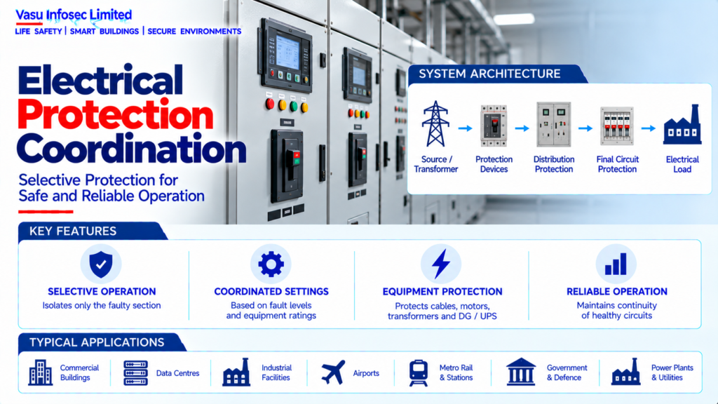
Electrical protection coordination selects and sets protective devices so faults can be detected and isolated selectively while healthy circuits remain in service where practicable. The study considers fault levels, equipment ratings, protection curves and the distribution hierarchy.
1. Engineering Overview
Electrical Protection Coordination is the systematic selection and setting of protective devices so that electrical faults are detected and isolated as quickly and selectively as practicable, while maintaining continuity of healthy circuits. The coordination study considers fault levels, equipment ratings, protection characteristics, time-current curves and the complete electrical distribution hierarchy.
2. Complete Protection Coordination Architecture
Utility / HT Source → HT Protection → Transformer → LT Main Protection → Distribution Protection → Final Circuit Protection → Electrical Load
Fault Detection → Protective Relay / Breaker → Trip Signal → Fault Isolation
Study Inputs → Load Flow → Short-Circuit Level → Equipment Ratings → Protection Curves → Coordination Study → Final Settings
3. Protection Objectives
The principal objectives are personnel and equipment protection, fault isolation, selective operation, system stability, appropriate backup protection and minimisation of unnecessary service interruption.
4. Protection Hierarchy
Protection should be arranged hierarchically from the final circuit towards the source. Downstream protective devices should generally clear local faults before upstream devices, while upstream protection provides backup when required.
5. Selectivity
Selectivity means that the protective device closest to the fault operates preferentially, allowing unaffected portions of the electrical system to remain energised. The achievable selectivity depends on device characteristics, fault level and manufacturer limitations.
6. Discrimination
Discrimination is achieved by coordinating the operating characteristics of protective devices so that their responses remain appropriately separated for the expected fault conditions. Time, current and energy characteristics may all be relevant.
7. Circuit Breaker Coordination
Breaker coordination considers rated current, short-circuit capacity, long-time pickup, short-time pickup, instantaneous operation and time delays as applicable. Settings should remain within equipment and cable protection limits.
8. Protective Relays
Protective relays detect abnormal electrical conditions and issue trip commands to circuit breakers. Relay functions and settings should be selected according to the protected equipment, system topology and fault characteristics.
9. Overcurrent Protection
Overcurrent protection responds to currents exceeding defined operating thresholds. Long-time and short-time characteristics should be coordinated with cable ampacity, transformer capacity, motor starting current and downstream protection.
10. Earth-Fault Protection
Earth-fault protection detects current flowing through an unintended earth path. Settings should provide adequate sensitivity while avoiding nuisance operation during normal system conditions.
11. Short-Circuit Protection
Short-circuit protection must interrupt prospective fault currents within the equipment’s rated capability and before unacceptable thermal or mechanical damage occurs.
12. Transformer Protection Coordination
Transformer protection should be coordinated with upstream HT protection and downstream LT protection. Transformer inrush, rated current, fault contribution and thermal limits should be considered when establishing settings.
13. Generator Protection Coordination
DG protection should account for the generator’s lower fault contribution compared with utility sources, transient characteristics and the generator’s thermal limits. Protection should coordinate with AMF, synchronising and downstream distribution systems.
14. Motor Protection Coordination
Motor circuits require protection against overload, short circuit and other applicable abnormal conditions while permitting normal starting current. Motor starting curves should be considered during coordination.
15. UPS Protection Coordination
UPS systems have different short-circuit characteristics from conventional transformers and generators. Upstream and downstream protection should therefore be coordinated using the UPS manufacturer’s fault-current and protection data.
16. Cable Protection
Protective-device settings should ensure that cables are protected against overload and short circuit. Cable ampacity, installation conditions and short-circuit withstand should be included in the coordination assessment.
17. Equipment Short-Circuit Rating
Switchboards, breakers, busbars, cables, transformers and other equipment must have ratings suitable for the prospective fault current at their installation points. The study should verify equipment withstand and interrupting capacities.
18. Time-Current Curves
Time-current characteristic curves are used to compare protective-device operating behaviour. Curves should be assessed across the relevant current range to identify coordination, overlap and potential nuisance-trip conditions.
19. Instantaneous Protection
Instantaneous protection can provide rapid fault clearing but may reduce selectivity if upstream and downstream devices have overlapping instantaneous operating regions. Settings should therefore be reviewed against the actual fault-current range.
20. Short-Time Delay
Short-time delay can be used to improve selectivity between upstream and downstream breakers. The delay must remain within the protected equipment’s withstand capability and applicable protection requirements.
21. Arc-Flash Consideration
Protection settings influence fault-clearing time and therefore may affect incident-energy exposure. Where an arc-flash assessment is required, the coordination study should be aligned with the approved safety analysis.
22. Protection Study Inputs
Typical inputs include:
- Single-line diagram
- Load schedule
- Transformer data
- Generator data
- UPS data
- Cable schedule
- Busbar ratings
- Protective-device data
- CT / VT data
- Motor data
- Utility fault-level information
- Earthing system
- Operating modes
23. Operating Modes
Protection coordination should consider relevant operating modes such as utility supply, DG supply, multiple-DG operation, transformer configurations, bus coupler operation, maintenance arrangements and other approved source combinations.
24. Short-Circuit Study
The short-circuit study establishes prospective fault currents at relevant electrical buses and feeders. These values are essential for breaker selection, equipment ratings and protection-setting verification.
25. Protection Setting Workflow
Typical workflow:
Collect System Data → Develop / Verify Single-Line Diagram → Perform Load Flow → Calculate Short-Circuit Levels → Select Protective Devices → Plot Time-Current Curves → Check Selectivity → Check Equipment & Cable Protection → Review Operating Modes → Finalise Settings → Document & Approve.
26. Installation Requirements
Installation should verify:
- Correct protective-device ratings
- Correct breaker / relay models
- Correct CT ratios
- Correct protection settings
- Correct trip-unit configuration
- Correct cable and equipment ratings
- Correct interlocking
- Correct source configuration
- Correct labels and setting records
- Protection settings consistent with approved study
27. Testing & Commissioning
Protection commissioning should verify:
- Relay configuration
- CT polarity and ratio
- Trip-unit settings
- Secondary injection where applicable
- Primary injection where required
- Breaker trip operation
- Interlocking
- Alarm / indication
- Source-transfer operation
- Protection communication
- Recorded final settings
28. Maintenance
Maintenance should include periodic verification of protection settings, relay health, breaker mechanisms, trip units, CT circuits, communication interfaces and event records. Unauthorised setting changes should be prevented and investigated.
29. Failure & Recovery
The system should be assessed for relay failure, breaker failure, incorrect settings, CT circuit faults, communication failure and nuisance tripping. Backup protection and controlled recovery procedures should be established.
30. Design Change Control
Changes to transformer ratings, DG sets, UPS systems, cables, switchboards, utility fault levels, source configurations or major loads should trigger a protection-coordination review.
31. Documentation
Protection coordination documentation should include, as applicable:
- Approved single-line diagram
- Load-flow study
- Short-circuit study
- Protection coordination study
- Time-current curves
- Equipment short-circuit ratings
- Relay setting sheets
- Breaker setting sheets
- CT / VT details
- Operating-mode assessment
- Arc-flash assessment where required
- Testing and commissioning records
- Final approved settings
- As-built drawings
32. Engineering Objective
The engineering objective is:
Establish System Topology → Determine Fault Levels → Identify Equipment & Cable Limits → Select Protective Devices → Develop Time-Current Coordination → Verify Selectivity & Backup Protection → Check All Operating Modes → Finalise Settings → Test & Document → Establish Safe, Selective & Reliable Electrical Fault Protection
Frequently Asked Questions
What is selectivity?
The protective device closest to a fault operates preferentially, allowing unaffected system parts to remain energised.
What inputs are needed for a coordination study?
Single-line diagrams, load schedule, equipment data, cable and busbar ratings, protective-device data, CT/VT data, utility fault levels, earthing and operating modes.
Why assess all operating modes?
Utility, DG, transformer and bus-coupler configurations can change fault levels and protection behaviour.
SEO & Publishing Details
| Field | Suggested website content |
| SEO title | Electrical Protection Coordination | Electrical Engineering Guide |
| Meta description | Learn about electrical protection coordination, including architecture, design considerations, installation, testing, maintenance and documentation. |
| Primary keyword | electrical protection coordination |
| Secondary keywords | electrical protection coordination architecture, electrical protection coordination design, electrical protection coordination testing, electrical and power systems |
| Suggested URL slug | electrical-protection-coordination |
| Suggested image alt text | Illustration of electrical protection coordination architecture and main components |