
Article
ELV Systems: Complete Architecture
Oct 2026
Direct Answer
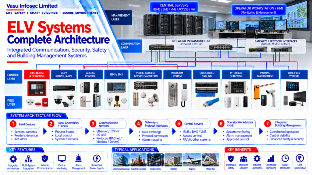
Extra-Low Voltage (ELV) systems bring together building communication, safety, security, monitoring and automation technologies. A complete ELV architecture defines how field devices, local panels, networks, gateways, servers and operator interfaces connect and exchange approved information. The final arrangement depends on the project scope, approved design, system requirements and interface responsibilities.
1. Engineering Overview
Extra-Low Voltage (ELV) systems comprise low-voltage communication, security, safety, monitoring and building automation systems that support building operations, life safety, security and information exchange. A complete ELV architecture establishes the equipment hierarchy, communication infrastructure, field devices, servers, workstations and interfaces required for coordinated system operation.
2. Complete ELV Architecture
Field Devices → Local Controllers / Panels → Communication Network → Gateways / Protocol Interfaces → Central Servers → Operator Workstations / HMI → Monitoring & Management
Typical Systems → Fire Alarm → CCTV → Access Control → IBMS / BMS → Public Address / Voice Evacuation → Structured Cabling → Intercom → Intrusion Detection → Other Project-Specific ELV Systems
3. ELV System Categories
Depending on project requirements, ELV architecture may include:
- Fire alarm and detection
- CCTV surveillance
- Access control
- IBMS / BMS
- Public address / voice evacuation
- Intercom systems
- Structured cabling
- Intrusion detection
- Parking management
- Time attendance
- Visitor management
- Audio-visual systems
- Other integrated building systems
4. Field Layer
The field layer consists of sensors, detectors, readers, cameras, switches, meters, actuators, controllers and other devices that collect information or execute commands. Device selection should be based on the approved system design and application requirements.
5. Control Layer
Local panels and controllers process field inputs and provide local control functions. Depending on the system, this layer may include fire alarm panels, access controllers, HVAC controllers, lighting controllers and other dedicated control equipment.
6. Communication Layer
The communication layer provides connectivity between field controllers, gateways, servers and operator interfaces. Common technologies may include Ethernet / TCP-IP, RS-485 and application-specific protocols such as BACnet or Modbus.
7. Gateway & Protocol Interface
Gateways may be used where different systems require protocol conversion or controlled data exchange. Gateway configuration should maintain the approved data points, alarm mapping, command permissions and communication reliability.
8. Server & Application Layer
Central servers may host IBMS, BMS, video management, access control or other applications. Server architecture should be based on the approved system capacity, redundancy requirements, database requirements and cybersecurity provisions.
9. Operator Workstation & HMI
Operator workstations provide central visibility of system status, alarms, trends, graphics and authorised control functions. HMI design should present clear system information and follow the approved graphics and alarm philosophy.
10. Network Architecture
ELV network architecture should define network topology, switches, VLANs where applicable, addressing, communication paths, fibre / copper infrastructure and network interfaces. Segregation should be implemented where required by the approved IT / cybersecurity architecture.
11. Fire & Life Safety Integration
Fire alarm and life safety systems may interface with other ELV systems for approved monitoring or control functions. Critical fire alarm functions should remain governed by the dedicated fire alarm architecture and approved Cause and Effect logic.
12. Security System Integration
CCTV, access control and other security systems may exchange approved status and event information with central management platforms. Integration should define authorised commands, event mapping and operator permissions.
13. IBMS Integration
IBMS can provide a central supervisory platform for approved building systems. Integration may include HVAC, electrical monitoring, lighting, fire alarm status, access control and other designated systems through approved interfaces.
14. Data & Point Architecture
Each integrated system should have a defined point list identifying device tags, data types, status points, alarms, commands, scaling and communication addresses. The point schedule should remain aligned with the approved drawings and software configuration.
15. Alarm Management
Alarm architecture should define alarm priorities, annunciation, acknowledgement, escalation, event logging and reset behaviour. Critical alarms should be distinguishable from routine status information.
16. Power Supply Architecture
ELV equipment should be provided with the required normal and standby / UPS power supplies as defined by the approved design. Critical systems should have appropriate power continuity and monitoring arrangements.
17. Installation Requirements
Installation should verify:
- Correct field devices
- Correct panels and controllers
- Correct communication cabling
- Correct network equipment
- Correct addressing
- Correct gateway interfaces
- Proper equipment identification
- Adequate access and maintenance clearance
- Correct power supply
- Proper segregation of services
18. Testing & Commissioning
ELV commissioning should verify:
- Field device operation
- Panel / controller operation
- Communication connectivity
- Network performance
- Gateway communication
- Point mapping
- Alarm generation
- Command operation
- HMI / graphics
- Data logging
- System interfaces
19. Cybersecurity & Access Control
Network-connected ELV systems should incorporate the approved cybersecurity and access-control measures. User accounts, permissions, network segregation, password management and remote access should follow the project-approved IT / cybersecurity requirements.
20. Maintenance & System Availability
Maintenance should cover field devices, panels, controllers, network equipment, servers, workstations, software, communication links and interfaces. Backup, configuration management and documented restoration procedures should be maintained for critical systems.
21. Design Change Control
Changes to ELV devices, network architecture, communication protocols, server configuration, point lists, interfaces or system functionality should be reviewed against the approved design before implementation.
22. Documentation
ELV documentation should include, as applicable:
- System architecture drawings
- Equipment schedules
- Device schedules
- Network architecture
- Communication architecture
- Point lists
- Cause and Effect Matrix
- Gateway / protocol mapping
- Server and workstation details
- Testing and commissioning records
- As-built drawings
- O&M manuals
23. Engineering Objective
The engineering objective is:
Reliable Field Devices → Local Control → Secure Communication Network → Controlled Integration → Central Monitoring → Clear HMI / Graphics → Verified Alarms & Commands → Complete Testing → Maintainable Architecture → Reliable ELV System Operation
Frequently Asked Questions
What are ELV systems?
ELV systems are building technologies for communication, security, safety, monitoring and automation, such as CCTV, access control, intercom, structured cabling and selected building management interfaces.
What are the main layers of an ELV architecture?
A typical architecture includes field devices, local controllers or panels, communication networks, gateways or protocol interfaces, central servers and operator workstations or HMIs.
Which systems can be integrated into IBMS?
Depending on the approved project design, IBMS may supervise HVAC, electrical monitoring, lighting, fire alarm status, access control and other designated systems through approved interfaces.
Why are point lists and interface schedules important?
They define device tags, data types, status points, alarms, commands, scaling and communication addresses, helping keep drawings, software configuration and commissioning aligned.
How should fire alarm integration be handled?
Fire alarm and life-safety interfaces should follow the dedicated fire alarm architecture and approved Cause and Effect logic. Critical fire alarm functions must remain governed by the approved design.
What should ELV commissioning verify?
Typical checks include device operation, panel/controller function, communications, network performance, point mapping, alarms, commands, HMI graphics, data logging and system interfaces, as applicable.
SEO & Publishing Details
| SEO title | ELV Systems Complete Architecture: Layers, Integration & Commissioning |
| Meta description | Understand complete ELV systems architecture, including field devices, controllers, networks, gateways, servers, IBMS integration, cybersecurity and commissioning. |
| Primary keyword | ELV systems architecture |
| Secondary keywords | ELV system integration, IBMS architecture, BMS integration, CCTV and access control integration, ELV network design, ELV commissioning |
| Suggested URL slug | /insights/elv-systems-complete-architecture/ |
| Suggested image alt text | Block diagram showing ELV field devices, controllers, communication network, gateways, central servers and operator workstations |