
Article
Fire Alarm Interfaces with HVAC, Lift & Access Control
Oct 2026
Direct Answer
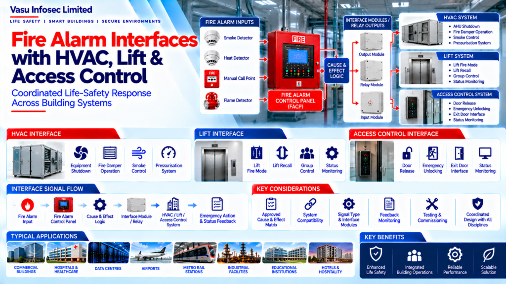
Fire alarm interfaces with HVAC, lifts and access control coordinate approved emergency actions when a fire alarm condition occurs. The initiating condition, output signal, receiving-system response, required feedback and reset/restoration sequence should be defined in the approved Cause & Effect Matrix and coordinated with the relevant system designs, manufacturers and project requirements.
1. Engineering Overview
Fire Alarm interfaces with HVAC, lift and access control systems provide coordinated life-safety responses when a fire alarm condition occurs. The interface philosophy should be established through the approved Cause & Effect Matrix and coordinated with the respective system designs, manufacturers and project requirements.
2. Integrated Interface Architecture
Fire Detection / MCP → Fire Alarm Control Panel → Cause & Effect Logic → Interface Module / Relay → HVAC / Lift / Access Control System → Defined Emergency Action → Status / Feedback to Fire Alarm System, where required
3. Interface Design Principle
The Fire Alarm System should act as the initiating life-safety signal source for approved interface actions. Each interface should clearly define the initiating condition, control output, receiving system response, feedback requirements and reset / restoration sequence.
4. HVAC Interface
A fire alarm condition may initiate selected HVAC control actions to limit smoke movement and support the approved fire strategy.
Typical actions may include:
- Shutdown of selected air-handling equipment
- Shutdown of supply / return fans
- Fire damper operation
- Smoke control interface
- Pressurisation system interface
- Equipment status monitoring
5. HVAC Cause & Effect
The Cause & Effect Matrix should identify which fire alarm zones, devices or conditions initiate HVAC actions. The exact sequence should be coordinated with the mechanical design and approved smoke-control strategy.
6. HVAC Feedback & Monitoring
Where required, the Fire Alarm System may monitor feedback from HVAC equipment or associated control systems.
Potential feedback conditions include:
- Equipment running / stopped status
- Damper position
- System fault
- Interface fault
- Smoke control status
7. Lift Interface
A fire alarm condition may initiate the approved lift emergency operation or fire mode. The exact response depends on the lift system design, building fire strategy and applicable requirements.
8. Lift Cause & Effect
The Cause & Effect Matrix should define:
- Initiating fire alarm condition
- Affected lift / lift group
- Required fire mode or recall action
- Interface signal
- Feedback, where required
- Reset / restoration sequence
9. Access Control Interface
A fire alarm condition may initiate release of selected access-controlled doors or other approved emergency access functions to support safe evacuation and emergency response.
10. Access Control Cause & Effect
The interface should identify the affected doors, access-control groups or areas and define the required emergency action.
Typical actions may include:
- Door release
- Emergency unlocking
- Controlled access release
- Emergency exit interface
- Status monitoring
11. Interface Modules & Relays
Fire alarm interfaces may use approved input / output modules, relay modules or dedicated interface equipment. The selected interface arrangement should be compatible with both the Fire Alarm System and the receiving equipment.
12. Signal Types
Interface signals may include:
- Fire alarm output
- Shutdown command
- Release command
- Supervisory signal
- Fault signal
- Status feedback
- Reset signal
The actual signal type should follow the approved system architecture.
13. Cause & Effect Coordination
The interface Cause & Effect Matrix should be developed jointly with relevant disciplines.
Coordination should include:
- Fire alarm engineering
- HVAC engineering
- Lift engineering
- Access control engineering
- Electrical engineering
- BMS / IBMS integration
14. Interface Testing & Commissioning
Integrated testing should verify the complete signal path and final system response.
Testing may include:
- Fire alarm initiation
- HVAC shutdown / control
- Fire damper response
- Lift fire mode
- Access control release
- Feedback signals
- Fault indication
- Cause & Effect verification
- Reset and restoration
15. Interface Failure & Fault Monitoring
Interface circuits should be monitored for applicable faults. Where feedback is required, the Fire Alarm System should provide appropriate indication when the receiving system does not achieve the expected condition.
16. Common Engineering Considerations
Engineering review should verify:
- Approved Cause & Effect Matrix
- Interface responsibilities
- Correct signal type
- Relay / module compatibility
- Receiving-system requirements
- Feedback requirements
- Fire strategy coordination
- Testing methodology
- Reset sequence
- Documentation consistency
17. Documentation
Interface documentation should include, as applicable:
- Interface architecture
- Cause & Effect Matrix
- HVAC interface schedule
- Lift interface schedule
- Access control interface schedule
- Input / Output schedule
- Wiring diagrams
- Interface module datasheets
- Testing records
- Commissioning records
- As-built documentation
18. Engineering Objective
The engineering objective is:
Reliable Fire Alarm Initiation → Correct Interface Logic → Coordinated HVAC Response → Correct Lift Fire Mode → Effective Access Control Release → Verified Feedback / Fault Monitoring → Integrated Testing → Reliable Life-Safety System Coordination
Frequently Asked Questions
What is a fire alarm interface?
It is a coordinated signal path through which an approved fire alarm condition triggers a defined action in another system, with feedback where required.
Which systems are covered in this resource?
The resource covers HVAC, lift and access control interfaces, together with interface modules/relays, signal types, Cause & Effect coordination, fault monitoring, testing and documentation.
Does every fire alarm automatically shut down HVAC or release every door?
No universal action is specified here. The affected equipment, doors and required response must follow the approved Cause & Effect Matrix, fire strategy, system design and project requirements.
Who should coordinate the interface sequence?
The source calls for joint coordination among fire alarm, HVAC, lift, access control, electrical and BMS/IBMS engineering disciplines, with the relevant manufacturers and project requirements taken into account.
What should integrated testing verify?
Testing should verify the complete signal path and final system response, including the relevant initiation, control action, feedback/fault indication and reset/restoration sequence.
SEO & CMS Publication Metadata
| SEO title | Fire Alarm Interfaces with HVAC, Lifts & Access Control | Engineering Guide |
| Meta description | Understand fire alarm interfaces with HVAC, lifts and access control, including Cause & Effect coordination, signal types, feedback, fault monitoring and integrated testing. |
| Suggested URL slug | /fire-alarm-interfaces-hvac-lifts-access-control/ |
| Primary keyword | fire alarm interfaces with HVAC, lifts and access control |
| Related keywords | fire alarm Cause & Effect Matrix; HVAC fire alarm interface; lift fire mode interface; access control fire alarm release; fire alarm interface testing |
| Suggested internal links | Fire Alarm System Architecture; Fire Alarm Cause & Effect Matrix; Fire Alarm Loop Architecture; Fire Alarm Testing and Commissioning |