
Article
Fire Protection Pipe Sizing & Pressure Loss
Oct 2026
Direct Answer
Fire protection pipe sizing determines the pipe diameters needed to convey the design water flow while maintaining the required residual pressure at the discharge devices. The sizing must be established through the approved hydraulic calculation, accounting for flow, velocity, pipe friction, fitting and valve losses, elevation effects and the available water supply.
1. Engineering Overview
Fire Protection Pipe Sizing & Pressure Loss establishes the appropriate pipe diameters and hydraulic characteristics required to convey the design fire water flow from the water supply to the designated fire protection discharge devices. Pipe sizing should be coordinated with the approved hydraulic calculation, system demand, available pressure and selected fire protection equipment.
2. Hydraulic Architecture
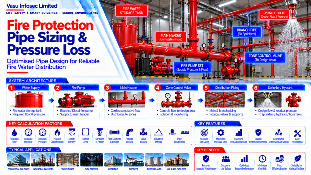
Fire Water Storage → Fire Pump → Main Header → Zone Control Assembly → Main Distribution Pipe → Branch Pipe → Sprinkler / Hydrant / Hose Reel
Hydraulic Inputs → Flow → Pipe Diameter → Velocity → Friction Loss → Fitting Loss → Elevation Loss → Available Residual Pressure
3. Design Inputs
Pipe sizing should consider:
- Required flow
- Available pressure
- Required residual pressure
- Pipe material
- Internal pipe diameter
- Pipe length
- Fittings
- Valves
- Elevation difference
- Hazard classification
- Design density / demand
4. Pipe Diameter Selection
Pipe diameter should be selected to convey the required design flow while maintaining acceptable hydraulic performance. Final pipe sizes should be established through the approved hydraulic calculation rather than by nominal sizing alone.
5. Flow & Velocity
Water flow through a pipe is related to the available cross-sectional area and flow velocity. Excessive velocity can increase friction losses and may affect system performance, while unnecessarily oversized piping can increase project cost and installation complexity.
6. Friction Pressure Loss
Friction pressure loss occurs as water flows through the internal surface of the pipe. The calculated loss depends on flow, pipe diameter, pipe material characteristics and pipe length.
7. Pipe Roughness
Pipe internal roughness influences hydraulic resistance. The calculation should use the appropriate coefficient or roughness value corresponding to the selected pipe material and approved hydraulic calculation method.
8. Fitting Losses
Elbows, tees, reducers, valves, check valves and other fittings introduce additional hydraulic losses. These losses should be included using the applicable fitting coefficients or equivalent pipe lengths.
9. Elevation Loss
Elevation changes affect available pressure within the fire protection network. Higher discharge points require additional pressure to overcome static head, and the hydraulic calculation should account for the complete elevation profile.
10. Main Pipe Sizing
Main distribution piping carries the cumulative flow from the design area or connected fire protection systems. Main pipe sizing should therefore consider the maximum applicable flow condition and the resulting pressure loss.
11. Branch Pipe Sizing
Branch piping distributes water to individual sprinkler heads or other discharge devices. Branch pipe sizing should maintain the pressure required at the design discharge devices while satisfying the approved hydraulic calculation.
12. Hydraulic Calculation Coordination
Pipe sizes should be directly coordinated with the hydraulic calculation. Any change in pipe diameter, routing, material or fitting arrangement can alter pressure loss and should be evaluated before implementation.
13. Residual Pressure
Residual pressure is the pressure available while water is flowing through the system. The calculated residual pressure at the design discharge devices should satisfy the approved fire protection design requirement.
14. Available Water Supply
The available water supply should be compared with the calculated system demand. The fire pump and water storage arrangement should provide adequate flow and pressure after accounting for pipe and component losses.
15. Pressure Loss Assessment
The total pressure loss should consider:
- Pipe friction
- Fitting losses
- Valve losses
- Elevation effects
- Equipment losses
- Other approved hydraulic components
16. Installation Requirements
Installation should verify:
- Correct pipe material
- Correct pipe diameter
- Correct routing
- Correct fittings
- Correct valves
- Proper supports
- Correct elevation coordination
- No unauthorised reductions in pipe size
- Correct identification and labelling
17. Testing & Commissioning
Testing should verify that the installed network performs in accordance with the approved design. Pump performance, flow conditions, pressure readings and relevant system test results should be reviewed against the hydraulic calculation.
18. Design Change Control
Changes to pipe size, pipe material, routing, fittings, valves, elevation, sprinkler locations or connected fire protection systems should be subjected to hydraulic review before approval and installation.
19. Documentation
Pipe sizing and pressure loss documentation should include, as applicable:
- Hydraulic calculation
- Pipe sizing schedule
- Hydraulic schematic
- Pipe material details
- Fitting schedule
- Valve schedule
- Pump performance curve
- Design assumptions
- Pressure loss results
- Approved piping drawings
- Testing records
- As-built drawings
20. Engineering Objective
The engineering objective is:
Accurate Fire Water Demand → Correct Pipe Diameter → Controlled Flow Velocity → Calculated Friction & Fitting Losses → Elevation Compensation → Adequate Residual Pressure → Verified Pump / Water Supply → Approved Hydraulic Network → Reliable Fire Protection Performance
Frequently Asked Questions
What determines fire protection pipe size?
The source identifies required flow and pressure, residual pressure, pipe material and internal diameter, pipe length, fittings, valves, elevation, hazard classification and design density/demand.
Which losses should be included in the hydraulic assessment?
Pipe friction, fitting losses, valve losses, elevation effects, equipment losses and other approved hydraulic component losses.
Why is residual pressure important?
Residual pressure is the pressure available while water is flowing. The calculated value at the design discharge devices must satisfy the approved fire protection design requirement.
Can pipe sizes be changed after calculation?
Any change to diameter, routing, material or fitting arrangement can alter pressure loss and should be hydraulically reviewed before implementation.
What should the documentation package include?
As applicable, the source lists hydraulic calculations, pipe sizing schedule, hydraulic schematic, pipe material details, fitting and valve schedules, pump curve, assumptions, pressure-loss results, approved piping drawings, test records and as-built drawings.
SEO & Website Publishing Details
| Suggested SEO title | Fire Protection Pipe Sizing & Pressure Loss | Vasu Infosec |
| Suggested meta description | Understand fire protection pipe sizing, flow velocity, friction and fitting losses, elevation effects, residual pressure and hydraulic verification. |
| Suggested URL slug | /fire-protection-pipe-sizing-pressure-loss/ |
| Primary keyword | fire protection pipe sizing |
| Secondary keywords | fire sprinkler pipe sizing; fire water pressure loss; pipe friction loss; residual pressure; hydraulic pipe calculation |
| Suggested category | Sprinkler & Hydraulics |
| Suggested image alt text | Fire protection piping network showing main and branch pipes, fittings, valves and hydraulic flow path |