
Article
Fire Pump Controller Architecture
Oct 2026
Direct Answer
A fire pump controller manages the approved automatic and manual operating functions of a fire pump, receives pressure-based start signals, indicates operating status and provides specified alarm or supervisory signals. Its selection, wiring, power supply and monitoring interfaces must be coordinated with the pump type, approved electrical and control design, and project Cause and Effect / monitoring schedules.
1. Engineering Overview
A Fire Pump Controller is the dedicated control and monitoring equipment associated with a fire pump. It provides the required automatic and manual operating functions, receives pressure-based start signals, indicates pump status and communicates applicable alarm or supervisory conditions to the designated fire protection monitoring system.
2. Controller Architecture
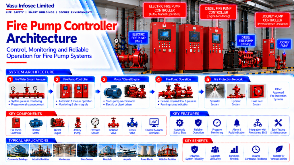
Fire Water System Pressure → Pressure Sensing Arrangement → Fire Pump Controller → Motor / Diesel Engine Start Command → Fire Pump Operation → System Pressure & Flow
Controller Monitoring → Power Supply → Pump Running → Fault / Alarm → Remote Monitoring Interface
3. Major Functions
A typical fire pump controller may provide:
- Automatic pump start
- Manual pump operation
- Pressure monitoring
- Pump running indication
- Power supply monitoring
- Fault indication
- Alarm / supervisory outputs
- Control circuit monitoring
- Status indication
- Remote interface signals
4. Automatic Start Philosophy
The controller receives the approved pressure-based starting signal when system pressure falls to the designated start condition. The controller then initiates the fire pump starting sequence in accordance with the approved fire pump control philosophy.
5. Manual Operation
Manual controls should allow authorised personnel to operate the fire pump from the controller when required. Manual operation should follow the approved operating procedure and should not compromise the automatic fire protection function.
6. Pressure Sensing
Pressure sensing devices or approved sensing arrangements provide the controller with the system pressure condition. Sensing connections should be installed, protected and maintained so that the controller receives reliable pressure information.
7. Electric Fire Pump Controller
For an electric fire pump, the controller interfaces with the pump motor and electrical supply to initiate and monitor pump operation. Controller selection should be coordinated with the motor rating and approved electrical design.
8. Diesel Fire Pump Controller
For a diesel fire pump, the controller interfaces with the engine starting system, batteries, chargers and engine monitoring functions. The controller should provide the required automatic starting and status indications.
9. Jockey Pump Controller Coordination
The jockey pump controller operates independently according to the approved pressure settings while remaining coordinated with the main fire pump controller. The pressure hierarchy should ensure that the jockey pump responds to minor pressure loss and the main pump starts during genuine fire demand.
10. Power Supply Monitoring
The controller should monitor the availability and condition of its required electrical supply. Where applicable, loss of normal power or other electrical abnormalities should generate the appropriate indication or alarm.
11. Pump Running Indication
Pump running status should be clearly indicated locally and, where required, transmitted to the fire alarm, BMS / IBMS or other approved monitoring system.
12. Alarm & Fault Monitoring
Applicable controller conditions may include:
- Power failure
- Motor / engine fault
- Controller fault
- Battery / charger fault
- Pump running
- Pressure condition
- Starting failure
- Communication fault
The final signals should follow the approved project Cause and Effect / monitoring schedule.
13. Interface with Fire Alarm System
Where required, the fire pump controller should provide status, alarm and supervisory signals to the fire alarm system. Interface points should be coordinated with the approved fire alarm architecture and Cause and Effect Matrix.
14. Interface with BMS / IBMS
Where BMS / IBMS monitoring is specified, controller status and alarm signals should be mapped to the approved interface schedule. The interface should not alter the required fire pump operating sequence unless specifically approved.
15. Installation Requirements
Installation should verify:
- Correct controller model
- Correct motor / engine compatibility
- Correct power supply
- Correct pressure sensing connection
- Correct control wiring
- Correct alarm / status interfaces
- Proper enclosure and environmental suitability
- Clear operating access
- Correct identification and labelling
16. Testing & Commissioning
Controller commissioning should verify:
- Automatic start
- Manual operation
- Pressure sensing
- Pump running indication
- Alarm indications
- Fault indications
- Power supply monitoring
- Remote status signals
- Fire alarm / BMS interfaces
- Complete Cause and Effect sequence
17. Functional Performance Verification
The controller should be tested together with the associated fire pump rather than as an isolated device. The complete sequence from pressure reduction through controller operation, pump starting and status indication should be verified.
18. Inspection & Maintenance
Periodic inspection should cover controller enclosure, indicators, control circuits, sensing connections, power supply, batteries / chargers where applicable, alarm signals and remote interfaces. Faults should be documented and rectified through the approved maintenance process.
19. Design Change Control
Changes to fire pump capacity, motor / engine, pressure settings, sensing arrangement, electrical supply, controller model or monitoring interfaces should be reviewed against the approved fire pump and control design before implementation.
20. Documentation
Fire pump controller documentation should include, as applicable:
- Controller datasheet
- Wiring / control schematic
- Pressure sensing details
- Motor / engine datasheet
- Electrical supply details
- Alarm and interface schedule
- Cause and Effect Matrix
- Factory test records
- Site commissioning records
- As-built drawings
- O&M manual
21. Engineering Objective
The engineering objective is:
Reliable Pressure Sensing → Correct Controller Decision → Automatic Fire Pump Start → Verified Pump Operation → Accurate Status & Fault Indication → Coordinated Fire Alarm / BMS Interface → Complete Testing → Reliable Fire Pump Control
Frequently Asked Questions
What does a fire pump controller do?
It provides the required automatic and manual operating functions, receives pressure-based start signals, indicates pump status and communicates specified alarm or supervisory conditions.
Do electric and diesel fire pump controllers have the same interfaces?
The source distinguishes electric controllers, which interface with the motor and electrical supply, from diesel controllers, which interface with the engine starting system, batteries, chargers and engine monitoring functions.
Which alarms or faults may be monitored?
The source lists power failure, motor/engine fault, controller fault, battery/charger fault, pump running, pressure condition, starting failure and communication fault. Final signals follow the approved project schedule.
How should fire alarm and BMS/IBMS interfaces be handled?
Where specified, status and alarm signals should be mapped to the approved interface schedule and Cause and Effect Matrix. The monitoring interface should not alter the required fire pump operating sequence unless specifically approved.
What should commissioning verify?
The source lists automatic start, manual operation, pressure sensing, running indication, alarms and faults, power monitoring, remote status signals, fire alarm/BMS interfaces and the complete Cause and Effect sequence.
SEO & Website Publishing Details
| Suggested SEO title | Fire Pump Controller Architecture & Monitoring | Vasu Infosec |
| Suggested meta description | Explore fire pump controller functions, automatic start, pressure sensing, electric and diesel interfaces, alarms, commissioning and monitoring. |
| Suggested URL slug | /fire-pump-controller-architecture/ |
| Primary keyword | fire pump controller architecture |
| Secondary keywords | fire pump controller; fire pump automatic start; fire pump alarm monitoring; diesel fire pump controller; fire alarm BMS interface |
| Suggested category | Sprinkler & Hydraulics |
| Suggested image alt text | Fire pump controller architecture showing pressure sensing, pump start command, status monitoring and remote alarm interfaces |