
Article
Gas Suppression Discharge Time Calculation
Oct 2026
Direct Answer
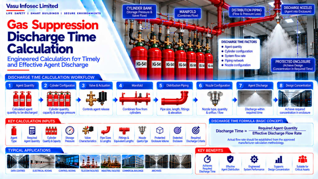
Gas suppression discharge-time calculation establishes how long an engineered system takes to deliver the required extinguishing-agent quantity into a protected enclosure. The result must be based on the selected agent, cylinder and valve configuration, manifold, actual piping network, nozzle arrangement and the approved manufacturer calculation methodology.
1. Engineering Overview
Gas Suppression Discharge Time Calculation determines the time required for the engineered suppression system to discharge the calculated quantity of extinguishing agent into the protected enclosure. The discharge time should be established from the selected agent, cylinder arrangement, piping network, nozzle configuration and approved manufacturer calculation methodology.
2. Discharge Time Architecture
Agent Quantity → Cylinder / Storage Configuration → Valve & Actuation → Manifold → Distribution Piping → Nozzle Flow → Agent Discharge → Required Design Concentration
3. Purpose of Discharge Time Calculation
The discharge time calculation verifies that the suppression system can deliver the required agent quantity within the specified design criteria and that the distribution system is capable of achieving the required concentration within the approved timeframe.
4. Calculation Inputs
Typical design inputs include:
- Agent type
- Required agent quantity
- Cylinder quantity and capacity
- Storage pressure
- Cylinder valve characteristics
- Manifold arrangement
- Pipe sizes
- Pipe lengths
- Fittings and equivalent lengths
- Nozzle quantity
- Nozzle configuration
- Protected enclosure volume
- Required discharge criteria
5. Agent Quantity Relationship
The required discharge time is directly related to the quantity of agent that must be delivered and the achievable system flow rate.
Discharge Time = Required Agent Quantity ÷ Effective Discharge Flow Rate
For engineered systems, the actual flow rate should be established from the approved manufacturer’s calculation methodology rather than from a simplified assumption.
6. Cylinder & Storage Configuration
Cylinder capacity, quantity, storage pressure and valve characteristics influence the available discharge flow. The selected cylinder bank should therefore be consistent with the approved discharge-time calculation.
7. Valve & Actuation Characteristics
The cylinder valve and actuation mechanism control the initiation of agent release. Their flow characteristics and operating configuration should be considered in the approved system calculation.
8. Manifold Flow
In multi-cylinder systems, agent from individual cylinders is combined through the manifold before entering the distribution network. Manifold configuration and pressure characteristics should be included in the approved flow calculation.
9. Piping Network Influence
Pipe diameter, length, fittings, elevation changes and branch configuration influence pressure loss and flow distribution. The actual engineered piping arrangement should be reflected in the discharge-time calculation.
10. Nozzle Flow Characteristics
Nozzle configuration and flow characteristics determine how the agent is discharged into the protected enclosure. Nozzle type, quantity and calculated configuration should correspond with the approved flow calculation.
11. Discharge Sequence
A typical sequence is:
Release Command → Valve / Actuator Operation → Agent Flow from Cylinders → Manifold Flow → Main Piping → Branch Piping → Nozzle Discharge → Agent Distribution within Protected Enclosure
12. Design Concentration & Discharge Time
The calculated discharge time should be evaluated against the required system design criteria and the time necessary to establish the intended concentration in the protected enclosure.
13. Flow Calculation Methodology
The exact calculation method depends on the selected gas suppression system and manufacturer. The approved calculation may use system-specific pressure, flow, pipe and nozzle characteristics. Manufacturer-approved software or calculation procedures should be used where specified.
14. Elevation Considerations
Changes in elevation within the piping network can affect flow characteristics. The actual pipe elevations and routing should therefore be incorporated into the approved calculation.
15. Nozzle Balance & Distribution
The discharge calculation should verify that the nozzle network provides the required distribution. Significant imbalance between branches or nozzles should be addressed through the engineered piping and nozzle design.
16. Calculation Verification
The completed calculation should verify:
- Correct agent quantity
- Correct cylinder configuration
- Correct storage pressure
- Correct valve characteristics
- Correct manifold arrangement
- Correct pipe sizes and lengths
- Correct fittings
- Correct nozzle configuration
- Required discharge performance
17. Testing & Commissioning
During commissioning, the installed system should be verified against the approved discharge-time design. Physical installation, cylinder configuration, piping, nozzle arrangement and Cause & Effect sequence should correspond with the approved calculation.
18. Design Change Control
Any change to cylinder quantity, storage pressure, valve type, pipe diameter, pipe routing, nozzle quantity or nozzle configuration may affect discharge time. Such changes should be technically reviewed and the calculation updated where required.
19. Documentation
Discharge-time documentation should include, as applicable:
- Approved design basis
- Agent quantity calculation
- Cylinder schedule
- Valve / actuator data
- Manifold details
- Piping / flow calculation
- Nozzle schedule
- Discharge-time result
- Manufacturer calculation output
- Testing / commissioning records
- As-built drawings
20. Engineering Objective
The engineering objective is:
Accurate Agent Quantity → Correct Cylinder & Valve Configuration → Verified Manifold Flow → Engineered Piping Network → Calculated Nozzle Flow → Validated Discharge Time → Achieved Design Concentration → Complete Technical Verification → Reliable Gas Suppression Performance
Frequently Asked Questions
What is gas suppression discharge time?
It is the time required for the engineered system to discharge the calculated quantity of extinguishing agent into the protected enclosure, assessed against the applicable approved design criteria.
What is the basic relationship used to express discharge time?
The source document gives: Discharge Time = Required Agent Quantity ÷ Effective Discharge Flow Rate. For engineered systems, the effective flow rate must come from the approved manufacturer calculation methodology.
Which inputs affect discharge time?
Inputs include agent type and quantity, cylinder quantity and capacity, storage pressure, valve characteristics, manifold arrangement, pipe sizes and lengths, fittings, elevation, nozzle quantity/configuration, enclosure volume and required discharge criteria.
Can discharge time be calculated using a generic flow rate?
No. The source specifies that actual flow rate should be established from the approved manufacturer calculation methodology rather than a simplified assumption.
Why do piping and nozzle changes matter?
Pipe diameter, length, fittings, elevation, branch configuration and nozzle characteristics affect pressure loss and flow distribution and can therefore affect the discharge-time result.
What records should be retained?
As applicable, retain the approved design basis, agent quantity calculation, cylinder schedule, valve/actuator data, manifold details, piping/flow calculation, nozzle schedule, discharge-time result, manufacturer calculation output, commissioning records and as-built drawings.
SEO & Website Publishing Details
SEO title: Gas Suppression Discharge Time Calculation: Key Inputs and Verification
Meta description: Understand gas suppression discharge-time calculation, key engineering inputs, cylinder and valve effects, piping and nozzle flow, verification and documentation.
Suggested URL slug: /engineering/gas-suppression-discharge-time-calculation/
Primary keyword: gas suppression discharge time calculation
Related keywords: gas suppression flow calculation; cylinder discharge time; clean agent system discharge; gas suppression piping and nozzle calculation
Suggested internal links: Gas Suppression Agent Quantity Calculation; Gas Suppression Cylinder Bank Architecture; Gas Suppression Piping Network Design & Installation; Gas Suppression Nozzle Arrangement & Coverage; Gas Suppression System Design Workflow