
Article
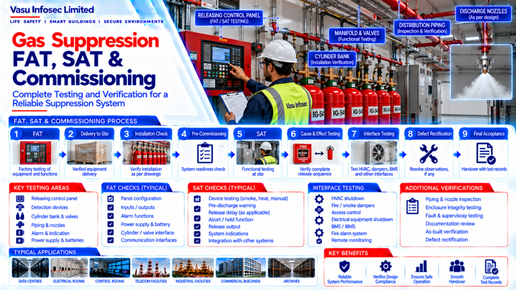
Gas Suppression FAT, SAT & Commissioning
Oct 2026
Direct Answer
Factory Acceptance Testing (FAT), Site Acceptance Testing (SAT) and commissioning are staged verification activities used to check that a gas suppression system is manufactured, installed, configured and integrated against the approved design, manufacturer requirements and project specifications.
1. Engineering Overview
Factory Acceptance Testing (FAT), Site Acceptance Testing (SAT) and commissioning verify that an engineered gas suppression system is manufactured, installed, configured and integrated in accordance with the approved design, manufacturer requirements and project specifications.
2. Overall Verification Flow
Approved Design → Equipment Manufacturing → FAT → Delivery → Site Installation → Installation Inspection → Pre-Commissioning → SAT → Cause & Effect Testing → Integrated Interface Testing → Defect Rectification → Final Acceptance → Handover
3. FAT Purpose
FAT provides factory-level verification of the suppression equipment and configured system before delivery to site. The scope should follow the approved FAT procedure and project inspection requirements.
4. FAT Scope
FAT may include verification of:
- Releasing control panel
- Detection interfaces
- Releasing outputs
- Alarm and indication functions
- Power supply
- Battery / charger functions
- Cylinder / valve interface
- Input / output modules
- Communication interfaces
- System configuration
5. FAT Documentation
FAT documentation may include:
- Approved FAT procedure
- Equipment datasheets
- Approved drawings
- Configuration records
- Test results
- Inspection records
- Observations / non-conformances, where applicable
- FAT approval / sign-off
6. Site Installation Verification
Following delivery, the installed suppression system should be inspected against approved drawings and equipment documentation.
Verification may include:
- Cylinder bank installation
- Valve / actuator arrangement
- Manifold
- Piping network
- Discharge nozzles
- Releasing panel
- Detection devices
- Alarm appliances
- Interfaces
7. Pre-Commissioning Checks
Before functional testing, the system should be checked for readiness.
Checks may include:
- Equipment installation
- Wiring and termination
- Device addressing
- Power supply
- Battery installation
- Cylinder / valve status
- Piping installation
- Nozzle installation
- Panel configuration
8. SAT Purpose
SAT verifies that the installed gas suppression system operates correctly at site and conforms to the approved design, configuration, Cause & Effect Matrix and installation requirements.
9. Detection Testing
Detection devices should be tested individually or according to the approved testing procedure.
Testing may include:
- Smoke detectors
- Heat detectors
- Aspirating detection interfaces
- Manual release
- Abort / hold function, where applicable
- Alarm indication
10. Releasing Logic Testing
The complete release sequence should be verified against the approved Cause & Effect Matrix.
Testing may include:
- First detection
- Confirmed detection / cross-zone logic, where applicable
- Pre-discharge warning
- Release delay
- Manual release
- Abort / hold function
- Release output
11. Cylinder & Valve Verification
Cylinder bank and valve arrangements should be verified for correct installation, identification, supervision and compatibility with the approved system configuration. Functional release testing should follow the approved procedure and should avoid unintended agent discharge.
12. Piping & Nozzle Inspection
The installed piping and nozzle arrangement should be checked against approved drawings and calculations.
Verification may include:
- Pipe size
- Routing
- Supports
- Fittings
- Nozzle type
- Nozzle location
- Nozzle orientation
- Obstruction clearance
13. Enclosure Integrity Verification
The protected enclosure should be verified for integrity and, where required, tested using the approved room integrity procedure. Any excessive leakage identified should be corrected and retested before final acceptance.
14. Interface Testing
Integrated testing may include interfaces with:
- HVAC
- Fire / smoke dampers
- Access control
- Electrical equipment shutdown
- BMS / IBMS
- Fire alarm system
- Remote monitoring
15. Cause & Effect Testing
The approved Cause & Effect Matrix should be tested from initiation through final system response. The actual site sequence should match the approved logic, including alarms, warnings, interfaces, release outputs and status indications.
16. Fault & Supervisory Testing
Applicable fault and supervisory conditions should be tested.
Examples include:
- Power supply fault
- Battery fault
- Detection circuit fault
- Releasing circuit fault
- Cylinder pressure supervision
- Interface fault
- Communication fault
17. Defect Rectification & Retesting
Defects or deviations identified during FAT, SAT or commissioning should be documented and rectified through the approved project process. Affected functions should be retested after corrective action.
18. Final Acceptance
Final acceptance should be based on satisfactory completion of required testing, closure of applicable observations and confirmation that the installed system matches the approved design and commissioning requirements.
19. Handover Documentation
Handover documentation should include, as applicable:
- Approved as-built drawings
- FAT records
- SAT records
- Commissioning report
- Cause & Effect Matrix
- Agent quantity calculation
- Flow / hydraulic calculation
- Cylinder schedule
- Nozzle schedule
- Enclosure integrity report
- O&M manual
- Warranty documentation
20. Engineering Objective
The engineering objective is:
Factory Verification → Site Installation Verification → Pre-Commissioning → SAT → Releasing Logic Verification → Integrated Interface Testing → Defect Closure → Final Acceptance → Complete Handover → Reliable Gas Suppression System Performance
Frequently Asked Questions
What is FAT in a gas suppression system?
FAT is factory-level verification of suppression equipment and configured system functions before delivery, following the approved FAT procedure and project inspection requirements.
What is SAT?
SAT verifies that the installed system operates correctly at site and conforms to the approved design, configuration, Cause & Effect Matrix and installation requirements.
What is checked during pre-commissioning?
Readiness checks may include installation, wiring and terminations, device addressing, power supply, batteries, cylinder and valve status, piping, nozzles and panel configuration.
Why is Cause & Effect testing important?
It verifies that the actual site sequence—from initiation through alarms, warnings, interfaces and release outputs—matches the approved Cause & Effect Matrix.
How should functional release testing be handled?
It should follow the approved procedure and be planned to avoid unintended agent discharge.
What records may be required at handover?
Applicable records may include as-built drawings, FAT and SAT records, commissioning reports, Cause & Effect Matrix, agent and flow calculations, cylinder and nozzle schedules, enclosure integrity report, O&M manual and warranty documentation.
SEO & Website Publishing Details
SEO title: Gas Suppression FAT, SAT and Commissioning: Verification Checklist
Meta description: Understand gas suppression FAT, SAT and commissioning, including detection and releasing logic tests, interfaces, defect rectification, acceptance and handover records.
Suggested URL slug: gas-suppression-fat-sat-commissioning
Primary keyword: gas suppression FAT SAT commissioning
Related keywords: gas suppression testing; releasing panel testing; Cause and Effect testing; gas suppression commissioning; enclosure integrity verification
Suggested internal links: Gas Suppression System Architecture; Gas Suppression Faults and Troubleshooting; Gas Suppression Discharge Time Calculation; Gas Suppression Hydraulic / Flow Calculation; Room Integrity / Enclosure Integrity Testing