
Article
Gas Suppression Piping Network Design & Installation
Oct 2026
Direct Answer
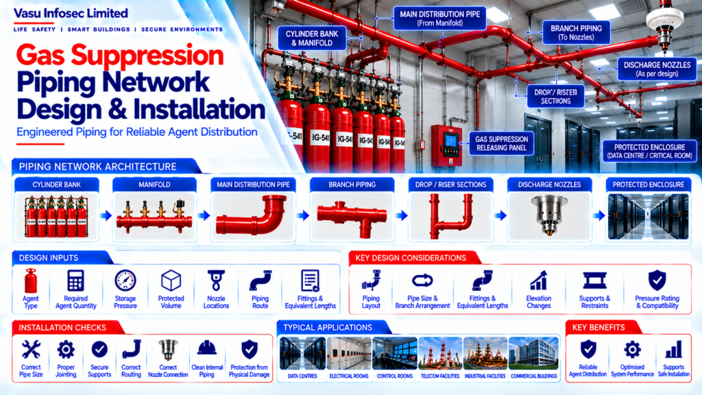
A gas suppression piping network carries the extinguishing agent from the cylinder bank and manifold through the main and branch piping to the discharge nozzles. Its design and installation should follow the approved system design and manufacturer calculation methodology, with pipe sizing, fittings, elevations, supports, component compatibility and nozzle connections coordinated and verified.
1. Engineering Overview
The gas suppression piping network transports the extinguishing agent from the cylinder bank and manifold to the discharge nozzles. The network must be engineered to provide the required flow distribution, discharge performance and mechanical integrity in accordance with the approved system design and manufacturer calculation methodology.
2. Piping Network Architecture
Cylinder Bank → Manifold → Main Distribution Pipe → Branch Piping → Drop / Riser Sections → Discharge Nozzles → Protected Enclosure
3. Design Inputs
Piping design should be based on verified inputs including:
- Agent type
- Required agent quantity
- Cylinder configuration
- Storage pressure
- Protected volume
- Nozzle quantity and locations
- Required discharge criteria
- Piping route
- Elevation differences
- Fittings and equivalent lengths
4. Piping Material Selection
Piping material, pressure rating, dimensions, fittings and joining method should be selected from the approved system design and manufacturer requirements. All components should be compatible with the selected agent and operating conditions.
5. Piping Layout
The piping layout should be developed to connect the cylinder manifold to all discharge nozzles while maintaining the approved hydraulic / flow calculation. Routing should be coordinated with structural, architectural, electrical, HVAC and other services.
6. Main & Branch Piping
The main pipe carries agent flow from the manifold and branches distribute the flow towards individual nozzles. Pipe sizes and branch arrangements should correspond with the approved flow calculation and nozzle schedule.
7. Fittings & Equivalent Lengths
Elbows, tees, reducers, couplings and other fittings affect system flow characteristics. The approved calculation should account for relevant fittings and equivalent pipe lengths in accordance with the selected manufacturer’s methodology.
8. Elevation & Routing Considerations
Changes in elevation can influence the flow behaviour of the agent. The actual installed routing and elevation should be reflected in the approved calculation, particularly where significant vertical sections are involved.
9. Pipe Supports & Restraints
Piping should be adequately supported and restrained to maintain alignment and mechanical stability. Support spacing, fixing method and restraint arrangement should follow approved installation details and project requirements.
10. Nozzle Connection
Each nozzle connection should correspond with the approved nozzle schedule and piping layout. Connections should provide correct orientation, secure fixing and compatibility with the selected nozzle.
11. Flow / Hydraulic Calculation
The piping network should be verified using the approved flow or hydraulic calculation methodology. The calculation should confirm that the system delivers the required flow to each nozzle within the specified discharge criteria.
12. Pressure Rating & Component Compatibility
All piping, fittings, valves, flexible connections and associated components should be suitable for the system operating and discharge conditions. Pressure ratings should be coordinated across the complete distribution network.
13. Installation Requirements
Installation should verify:
- Correct pipe size
- Correct routing
- Correct fittings
- Proper jointing
- Secure supports
- Correct elevation
- Correct branch connections
- Correct nozzle connections
- Protection from physical damage
- Clean internal piping condition
14. Piping Cleanliness
The piping network should be protected against contamination during storage and installation. Foreign material, moisture, debris and other contaminants should be prevented from entering the piping and nozzles.
15. Inspection & Quality Control
Inspection should verify that installed piping matches approved drawings and calculations.
Quality checks may include:
- Material verification
- Pipe size verification
- Fitting verification
- Routing inspection
- Support inspection
- Joint inspection
- Nozzle connection inspection
- Identification / labelling
16. Testing & Commissioning
Piping system verification may include applicable integrity, installation and functional checks. The final commissioning process should confirm correct nozzle arrangement, system connections, release sequence and correspondence with the approved design.
17. Design Changes & Site Coordination
Any change in pipe routing, pipe size, nozzle location, cylinder configuration or other system parameter should be reviewed against the approved calculation before implementation. Changes that affect system performance should be formally incorporated into the revised design documentation.
18. Common Engineering Considerations
Engineering review should verify:
- Correct agent compatibility
- Approved pipe material
- Pipe sizing
- Routing
- Fittings
- Equivalent lengths
- Elevation changes
- Supports and restraints
- Nozzle connections
- Flow calculation
- Installation quality
19. Documentation
Piping documentation should include, as applicable:
- Piping layout drawings
- Isometric drawings
- Pipe and fitting schedule
- Flow / hydraulic calculation
- Nozzle schedule
- Support details
- Installation method statement
- Inspection records
- Testing records
- As-built drawings
20. Engineering Objective
The engineering objective is:
Correct Design Inputs → Engineered Piping Route → Verified Pipe Sizing → Accurate Flow Calculation → Secure Supports & Connections → Correct Nozzle Integration → Controlled Installation → Complete Inspection & Testing → Accurate As-Built Documentation → Reliable Gas Suppression Agent Distribution
Frequently Asked Questions
What information is needed before designing the piping network?
Verified design inputs include agent type and quantity, cylinder configuration, storage pressure, protected volume, nozzle quantity and locations, discharge criteria, piping route, elevation differences, and fittings/equivalent lengths.
Why do fittings and elevation changes matter?
Fittings and changes in elevation affect flow characteristics. They should be represented in the approved calculation using the selected manufacturer’s methodology and the actual installed routing.
Can pipe routing or nozzle locations be changed at site?
Changes to routing, pipe size, nozzle location, cylinder configuration or other system parameters should be reviewed against the approved calculation before implementation. Performance-affecting changes should be incorporated into revised design documentation.
What should be checked during installation?
Checks include pipe size, routing, fittings, jointing, supports, elevation, branch and nozzle connections, protection from physical damage, and clean internal piping condition.
Which documents should be retained?
As applicable, retain piping layout and isometric drawings, pipe/fitting schedule, flow or hydraulic calculation, nozzle schedule, support details, installation method statement, inspection/testing records and as-built drawings.
SEO & Website Publishing Details
SEO title: Gas Suppression Piping Network Design and Installation | Vasu Infosec
Meta description: Understand gas suppression piping network architecture, design inputs, pipe sizing, fittings, elevations, supports, nozzle connections, installation checks and documentation.
Suggested URL slug: /gas-suppression-piping-network-design-installation/
Primary keyword: gas suppression piping network design
Related keywords: gas suppression piping installation; gas suppression pipe sizing; gas suppression nozzle piping; gas suppression flow calculation; cylinder manifold piping
Suggested internal links: Gas Suppression System Complete Architecture; Gas Suppression System Design Workflow; Gas Suppression System Nozzle Arrangement; Gas Suppression Cylinder Bank Architecture.