
Article
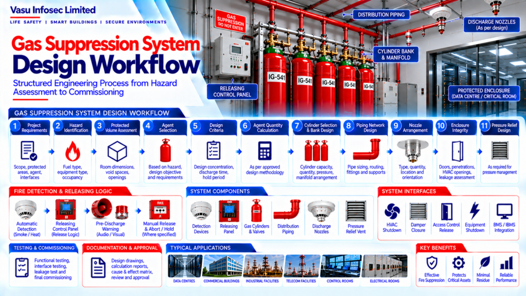
Gas Suppression System Design Workflow
Oct 2026
Direct Answer
A gas suppression system design workflow is a structured engineering process that moves from reviewing project requirements and identifying the hazard to calculating the agent quantity, designing distribution piping and nozzles, coordinating interfaces, testing the system, and handing over the final documentation. The design basis must follow approved project requirements, manufacturer criteria and applicable requirements.
1. Engineering Overview
The Gas Suppression System Design Workflow provides a structured engineering sequence from hazard identification and enclosure assessment through agent selection, system calculation, equipment selection, coordination, testing and final documentation. The workflow should be based on the approved fire strategy, project requirements, manufacturer design criteria and applicable requirements.
2. Overall Design Workflow
Project Requirements → Hazard Identification → Protected Volume Assessment → Agent Selection → Design Criteria → Agent Quantity Calculation → Cylinder Selection → Piping / Flow Design → Nozzle Arrangement → Enclosure Integrity → Pressure Relief → Cause & Effect → Coordination → Review / Approval → Installation → Testing & Commissioning → Handover
3. Project Requirement Review
The design process should begin with a review of the project specifications and technical requirements.
Review may include:
- Scope of work
- Protected areas
- Approved agent requirements
- Detection requirements
- Releasing requirements
- Interface requirements
- Testing requirements
- Documentation requirements
4. Hazard Identification
The hazard should be assessed to determine the type of fire risk, expected fire characteristics and required suppression approach.
Considerations may include:
- Fuel type
- Equipment type
- Occupancy
- Fire development characteristics
- Critical equipment
- Occupant considerations
- Environmental conditions
5. Protected Volume Assessment
The protected enclosure volume should be established from approved architectural and coordinated services information.
The assessment should consider:
- Room dimensions
- Ceiling voids
- Raised floors
- Permanent openings
- Protected subspaces
- Equipment displacement where applicable
6. Agent Selection
The suppression agent should be selected based on the hazard, design objective, environmental considerations, required concentration, storage arrangement and approved project requirements.
7. Design Criteria Establishment
The design criteria should define the engineering basis for the suppression system.
Typical criteria include:
- Design concentration
- Minimum / maximum design conditions
- Required discharge time
- Required hold period
- Ambient temperature
- Enclosure conditions
- Safety considerations
8. Agent Quantity Calculation
The required agent quantity should be determined using the approved design methodology and applicable manufacturer calculation procedure. The calculation should account for protected volume, agent characteristics, design concentration and relevant environmental conditions.
9. Cylinder Selection & Bank Design
Cylinder quantity, cylinder capacity, storage pressure and bank arrangement should be established from the calculated agent requirement and approved equipment range.
The design should verify:
- Cylinder capacity
- Quantity
- Storage pressure
- Temperature range
- Manifold arrangement
- Valve / actuator configuration
10. Piping Network Design
The distribution piping should be designed to transport the agent from the cylinder bank to the discharge nozzles within the required performance criteria.
Design considerations include:
- Pipe routing
- Pipe diameter
- Branch arrangement
- Fittings
- Elevation changes
- Equivalent lengths
- Supports
11. Hydraulic / Flow Calculation
The piping network should be verified using the approved hydraulic or flow calculation methodology applicable to the selected system. The calculation should confirm the required flow distribution, discharge timing and nozzle performance.
12. Nozzle Arrangement
Nozzle quantity, type, location, orientation and discharge characteristics should be established from the approved calculation and manufacturer design criteria. The arrangement should provide effective distribution throughout the protected enclosure.
13. Enclosure Integrity Assessment
The enclosure should be assessed for leakage paths that may affect agent retention.
The review should include:
- Doors
- Cable penetrations
- Pipe penetrations
- HVAC openings
- Dampers
- Construction joints
- Other permanent openings
14. Pressure Relief Design
Where required, pressure relief provisions should be designed to manage the pressure effects associated with agent discharge while maintaining the required enclosure performance.
15. Fire Detection & Releasing Logic
The detection and releasing philosophy should define how the system progresses from fire detection to controlled agent discharge.
The design may include:
- Detection zoning
- Cross-zone logic
- Pre-discharge warning
- Manual release
- Abort / hold function
- Release delay
- Interface actions
16. Building Services Coordination
The suppression system should be coordinated with relevant building services.
Coordination may include:
- HVAC
- Fire / smoke dampers
- Access control
- Electrical equipment
- BMS / IBMS
- Fire alarm system
- Remote monitoring
17. Design Review & Approval
The completed design should undergo technical review before procurement and installation.
Review should verify:
- Design calculations
- Equipment selection
- Cylinder configuration
- Piping design
- Nozzle arrangement
- Enclosure integrity
- Cause & Effect
- Interface requirements
- Compliance with approved specifications
18. Installation & Site Verification
Installation should follow approved drawings and manufacturer requirements. Site verification should confirm that the installed system matches the approved design and that changes in room configuration or services have been assessed.
19. Testing & Commissioning
Commissioning should verify the complete system sequence.
Testing may include:
- Detection testing
- Release logic testing
- Manual release
- Abort / hold function
- Alarm notification
- Interface testing
- Piping / nozzle inspection
- Enclosure integrity testing
- Cause & Effect verification
20. Documentation & Handover
Final documentation should include, as applicable:
- Approved design drawings
- Design calculations
- Agent quantity calculation
- Cylinder schedule
- Piping / flow calculation
- Nozzle schedule
- Cause & Effect Matrix
- Enclosure integrity report
- FAT / SAT records
- Commissioning records
- As-built drawings
- O&M manual
21. Engineering Objective
The engineering objective is:
Defined Hazard → Correct Design Basis → Accurate Volume Assessment → Appropriate Agent Selection → Verified Agent Quantity → Engineered Cylinder & Piping System → Optimised Nozzle Arrangement → Confirmed Enclosure Integrity → Coordinated Release Logic → Verified Testing → Complete Handover → Reliable Gas Suppression Protection
Frequently Asked Questions
What is the purpose of a gas suppression system design workflow?
It provides a traceable sequence for assessing the hazard and protected enclosure, establishing design criteria, calculating and selecting equipment, coordinating interfaces, verifying the installation, and completing testing and handover.
What information is needed before design begins?
The source identifies project scope and specifications, protected areas, approved agent requirements, detection and releasing requirements, interfaces, testing requirements and documentation requirements.
How is the required extinguishing-agent quantity determined?
The source states that quantity should be determined using the approved design methodology and applicable manufacturer calculation procedure, considering protected volume, agent characteristics, design concentration and relevant environmental conditions.
Why are enclosure integrity and pressure relief included in the workflow?
Leakage can affect agent retention, while discharge can create pressure effects. Both should be assessed and coordinated with the approved design where applicable.
What records may be included in handover documentation?
The source lists approved design drawings, calculations, agent quantity calculation, cylinder schedule, piping/flow calculation, nozzle schedule, Cause & Effect Matrix, enclosure integrity report, FAT/SAT records, commissioning records, as-built drawings and O&M manual, as applicable.
Does mentioning an applicable standard establish compliance?
No. The design should be checked against the specific approved project requirements, applicable requirements and manufacturer criteria. The source does not identify a particular standard edition or clause, so those details must be confirmed for the project.
SEO and Publication Details
| SEO title | Gas Suppression System Design Workflow | Engineering Guide |
| Meta description | Explore the gas suppression system design workflow, from hazard and enclosure assessment to agent calculations, piping, nozzles, testing and handover. |
| Suggested URL slug | /gas-suppression-system-design-workflow/ |
| Primary keyword | gas suppression system design workflow |
| Related keywords | gas suppression design; clean agent system design; agent quantity calculation; enclosure integrity; gas suppression commissioning |
| Suggested internal links | Gas Suppression System Architecture; Clean Agent Fire Suppression Working Principle; Fire Detection and Gas Release Logic; Gas Suppression Nozzle Arrangement; Gas Suppression Enclosure Integrity |