
Article
IBMS: Complete System Architecture
Oct 2026
Direct Answer
An Integrated Building Management System (IBMS) brings approved building-service information into a central supervisory platform. Its architecture connects field devices and local controllers with communication networks, gateways, servers, databases and operator interfaces so authorised users can monitor alarms, equipment status, trends and reports—and perform only those control functions included in the approved integration scope.
1. Engineering Overview
An Integrated Building Management System (IBMS) provides a central supervisory platform for monitoring and, where approved, controlling multiple building services through defined communication interfaces. The architecture establishes the field devices, controllers, communication network, gateways, servers, operator workstations, databases, graphics, alarms and reporting functions required for integrated building operations.
2. Complete IBMS Architecture
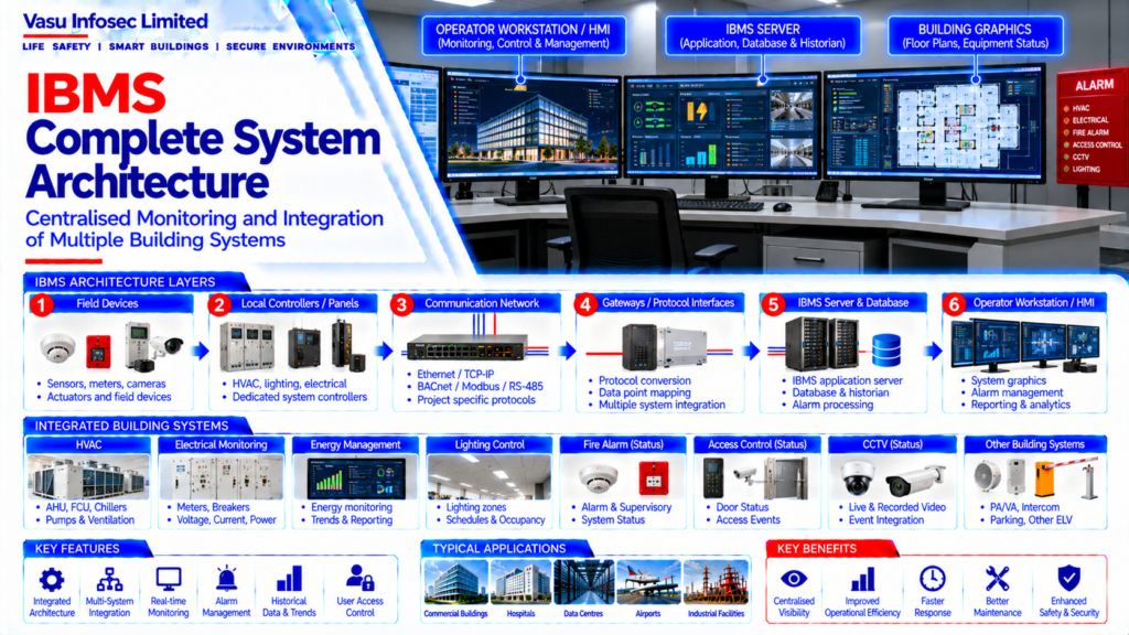
Field Sensors / Devices → Local Controllers / Panels → Communication Network → Protocol Gateways → IBMS Integration Server → Database / Application Server → Operator Workstation / HMI
Integrated Systems → HVAC → Electrical Monitoring → Energy Management → Lighting → Fire Alarm Status → Access Control Status → Other Approved Building Systems
3. Field Device Layer
The field layer includes sensors, meters, switches, actuators, controllers and other devices that generate operational data or receive approved commands. Device selection and installation should follow the relevant system design and manufacturer requirements.
4. Automation / Control Layer
Local controllers receive field information and execute dedicated control sequences. Examples may include HVAC controllers, electrical monitoring devices, lighting controllers and other building automation controllers.
5. Communication Layer
The communication layer connects local systems with IBMS servers and gateways. Depending on the project architecture, communication may use Ethernet / TCP-IP, BACnet, Modbus, RS-485 or other approved protocols.
6. Gateway & Integration Layer
Gateways provide controlled communication between systems using different protocols or architectures. Gateway configuration should define point mapping, data types, status information, alarm information and authorised commands.
7. IBMS Server Architecture
IBMS servers host the supervisory application, databases, communication services, alarm processing, historical data and user management functions. Server architecture should be sized for the approved number of systems, points, users and required performance.
8. Database & Historian
The IBMS database stores configuration and operational information. Historical data may include trends, alarms, events, energy information and equipment status. Data retention should follow the approved project requirements.
9. Operator Workstation & HMI
Operator workstations provide access to system graphics, equipment status, alarms, trends, reports and authorised control functions. HMI screens should provide clear navigation and consistent equipment representation.
10. Graphics Architecture
Graphics should represent the building hierarchy from site / building level through floors, zones, equipment and individual points. Equipment status, alarms and operating values should be clearly displayed.
11. Alarm Management
IBMS alarm management should provide defined alarm priorities, annunciation, acknowledgement, event logging and operator response. Critical alarms should be clearly distinguishable from routine status indications.
12. HVAC Integration
HVAC integration may include AHUs, FCUs, chillers, pumps, cooling towers, ventilation systems, temperature sensors, pressure sensors and other approved equipment. The IBMS should monitor and control only those points and functions defined in the approved integration scope.
13. Electrical Monitoring Integration
Electrical systems may be integrated for monitoring of breakers, meters, energy consumption, voltage, current, power, frequency and other approved parameters. Critical electrical protection functions should remain within the dedicated electrical protection architecture.
14. Energy Management
IBMS may collect energy data from electrical meters and other approved sources to provide consumption trends, demand monitoring, reporting and energy performance analysis. Energy control functions should follow the approved sequence and authority levels.
15. Lighting Integration
Lighting control systems may be integrated for monitoring and authorised control of lighting zones, schedules, occupancy-based functions and status information. The interface should follow the approved lighting control architecture.
16. Fire Alarm Integration
Fire alarm integration should normally provide approved status, alarm and supervisory information to IBMS. Dedicated fire alarm control functions should remain under the approved fire alarm system architecture unless a specific interface is authorised.
17. Access Control Integration
Access control systems may provide approved door, alarm and access-event information to IBMS. Integration should define the points and commands permitted through the central platform without compromising the dedicated access control system.
18. Network & Cybersecurity Architecture
The IBMS network should be designed with appropriate addressing, segmentation, communication security and access controls. Network architecture should be coordinated with the project’s IT and cybersecurity requirements.
19. User Management
IBMS user access should be role-based wherever applicable. User permissions should distinguish monitoring, acknowledgement, reporting, configuration and authorised control functions.
20. Power & Redundancy
Critical IBMS infrastructure should be provided with the approved power continuity and redundancy arrangement. Servers, network equipment and controllers should be supported according to the required system availability.
21. Installation Requirements
Installation should verify:
- Correct field devices
- Correct controllers
- Correct communication network
- Correct gateways
- Correct server configuration
- Correct point mapping
- Correct graphics
- Correct user permissions
- Correct alarm configuration
- Correct power supply
22. Testing & Commissioning
IBMS commissioning should verify:
- Field device values
- Controller communication
- Network connectivity
- Gateway communication
- Point mapping
- Alarm generation
- Command operation
- Graphics representation
- Trend logging
- Report generation
- System interfaces
23. Maintenance & Backup
Maintenance should include server health checks, database backup, configuration backup, network checks, controller checks, communication diagnostics, alarm review and software maintenance. Approved backup and restoration procedures should be maintained.
24. Design Change Control
Changes to integrated systems, point lists, protocols, gateways, network architecture, server configuration, graphics or control sequences should be reviewed against the approved IBMS architecture before implementation.
25. Documentation
IBMS documentation should include, as applicable:
- System architecture
- Integration architecture
- Network topology
- Point list
- Gateway mapping
- Communication protocol details
- Cause and Effect / control sequences
- Graphics philosophy
- Alarm philosophy
- Server architecture
- User access matrix
- Testing and commissioning records
- As-built drawings
- O&M manual
26. Engineering Objective
The engineering objective is:
Reliable Field Data → Local Control → Secure Communication → Controlled Integration → Centralised Monitoring → Accurate Graphics & Alarms → Authorised Control → Historical Data & Reporting → Complete Testing → Maintainable IBMS Architecture
Frequently Asked Questions
What is an Integrated Building Management System (IBMS)?
IBMS is a central supervisory platform for monitoring and, where approved, controlling multiple building services through defined communication interfaces.
What are the main layers of IBMS architecture?
A typical architecture includes field devices, local controllers, communication networks, protocol gateways, integration servers, databases or application servers, and operator workstations/HMI.
Which systems can be integrated with IBMS?
Depending on the approved project scope, integrations may include HVAC, electrical monitoring, energy management, lighting, fire alarm status and access control status.
What is the role of a gateway in IBMS?
A gateway enables controlled communication between systems that use different protocols or architectures, with point mapping and authorised commands defined for the project.
How should fire alarm integration be handled?
The source document states that IBMS should normally receive approved fire alarm status, alarm and supervisory information; dedicated fire alarm control functions remain governed by the approved fire alarm architecture unless a specific interface is authorised.
What documents support IBMS commissioning?
As applicable, documentation includes architecture and network drawings, point lists, gateway mapping, protocol details, control sequences, graphics and alarm philosophies, user access matrix, test records, as-built drawings and the O&M manual.
Website Publishing Details
SEO title: IBMS Complete System Architecture | Vasu Infosec Limited
Meta description: Understand IBMS architecture, including field devices, controllers, communication networks, gateways, servers, alarms, graphics, and approved building-system integration.
Suggested URL slug: /insights/ibms-complete-system-architecture/
Primary keyword: IBMS complete system architecture
Secondary keywords: Integrated Building Management System, IBMS integration, building automation architecture, IBMS gateway, IBMS monitoring, building management systems
Suggested image alt text: IBMS architecture diagram showing field devices, local controllers, communication network, protocol gateways, IBMS server, database and operator workstation.