
Article
LT Panel Architecture
Oct 2026
Direct Answer
An LT panel is a low-voltage switchboard that receives, controls, protects, meters and distributes power to downstream loads. Its design integrates incomers, busbars, outgoing feeders, protection, metering, controls, interlocks and cable terminations.
1. Engineering Overview
An LT Panel is a low-voltage electrical switchboard used to receive, control, protect, meter and distribute electrical power to downstream loads. Its architecture integrates incomers, busbars, outgoing feeders, protection devices, metering, control, interlocking, cable termination and auxiliary systems.
2. Complete LT Panel Architecture
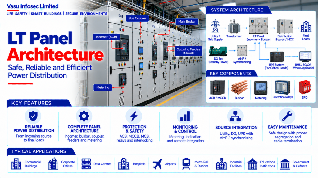
Transformer / DG / Utility Source → LT Panel Incomer → Main Busbar → Bus Coupler / Section → Outgoing Feeders → MCC / DB / Final Loads
Protection → ACB / MCCB / MCB / Protective Relays
Metering → Multifunction Meter / CTs / VTs, where applicable
Control → Local / Remote Controls → BMS / SCADA, where applicable
Supporting Systems → Earthing → Surge Protection → Auxiliary Power
3. Panel Incomer
The incomer receives power from the designated upstream source such as a transformer, DG set or utility supply. The incomer rating should be based on maximum demand, fault level, system voltage and required operating margin.
4. Main Busbar
The main busbar distributes incoming power to outgoing feeders and bus sections. Busbar current rating, short-circuit withstand, temperature rise and segregation should be selected according to the calculated system requirements.
5. Bus Coupler
A bus coupler may connect or isolate two bus sections to support source transfer, redundancy or operational flexibility. Electrical and mechanical interlocks should prevent unsafe switching sequences.
6. Outgoing Feeders
Outgoing feeders supply MCCs, distribution boards, HVAC systems, fire and life-safety systems, UPS systems and other electrical loads. Each feeder should have suitable protection and isolation.
7. Protection Architecture
LT panels may use ACBs, MCCBs, MCBs, fuses and protective relays depending on feeder capacity and application. Protection settings should coordinate with upstream and downstream devices.
8. Short-Circuit Rating
The panel should have an appropriate short-circuit withstand / breaking capacity based on the prospective fault current at its installation point. The rating should be verified through the electrical fault-level study.
9. Metering Architecture
Multifunction meters may monitor voltage, current, frequency, power, energy, power factor and other parameters. CT ratios and metering accuracy should match the approved metering requirements.
10. Current Transformers
CTs may be provided for metering and protection. CT ratio, class, burden, installation arrangement and secondary wiring should be selected according to the intended function.
11. Control & Indication
LT panels may include local control switches, push buttons, indication lamps, selector switches, status indications and alarms. The control philosophy should define local / remote operation where applicable.
12. Remote Monitoring
Where required, panel parameters and status signals may be communicated to BMS, SCADA or an electrical power monitoring system. Required points and communication protocols should be defined in the approved interface matrix.
13. Automatic Source Transfer
Where multiple sources are available, the LT panel may incorporate automatic source-changeover or AMF / ATS functions. Transfer and restoration logic should be coordinated with DG and upstream systems.
14. DG Integration
DG incomers may be connected to the LT panel through an AMF, synchronising or automatic transfer arrangement. Generator protection and source interlocking should be coordinated with the panel design.
15. UPS Integration
Critical loads may be supplied through dedicated UPS distribution sections. UPS incomers and critical-load feeders should be segregated and identified according to the approved critical-power architecture.
16. Earthing Arrangement
The panel enclosure and internal exposed conductive parts should be connected to the approved protective earthing system. Earthing continuity should be maintained throughout the panel assembly.
17. Surge Protection
Surge protection devices may be provided at appropriate distribution levels to protect connected equipment from transient overvoltage. SPD selection and coordination should follow the approved electrical protection design.
18. Panel Form & Segregation
Panel construction and internal segregation should be selected according to the required operational safety, maintenance access, fault containment and equipment arrangement. The approved panel specification should define the applicable form of separation.
19. Cable Entry & Termination
Cable entry may be from top or bottom depending on the installation. Adequate gland plates, termination space, bending radius, cable supports and identification should be provided.
20. Heat Dissipation
Panel thermal performance should account for internal heat generation from breakers, busbars, drives, meters and other components. Ventilation or other thermal-management arrangements should be provided where required.
21. Installation Requirements
Installation should verify:
- Correct panel rating
- Correct incomer arrangement
- Correct busbar rating
- Correct short-circuit rating
- Correct outgoing feeder configuration
- Correct protection settings
- Correct metering and CT ratios
- Correct source interlocking
- Correct cable termination
- Correct earthing
- Correct SPD arrangement
- Proper identification and labelling
22. Testing & Commissioning
LT panel commissioning should verify:
- Visual and mechanical inspection
- Insulation resistance
- Continuity
- Earth continuity
- Breaker operation
- Interlocks
- Protection operation
- Metering accuracy / indication
- Source-changeover operation, where applicable
- Remote monitoring signals
- Functional control tests
23. Maintenance
Maintenance should include panel cleaning, visual inspection, busbar and termination checks, breaker operation, protection verification, thermal inspection where appropriate, metering checks, earthing verification and control-circuit inspection.
24. Failure & Recovery
The panel should be assessed for incomer failure, feeder fault, bus-section fault, source-transfer failure and control-power failure. Recovery procedures should be defined and tested according to the approved operating philosophy.
25. Design Change Control
Changes to load demand, feeder quantity, source capacity, fault level, breaker ratings, protection settings, busbar arrangement or panel configuration should trigger a technical review.
26. Documentation
LT panel documentation should include, as applicable:
- Single-line diagram
- Panel GA / layout
- Panel schedule
- Incomer / feeder schedule
- Busbar calculation
- Short-circuit study
- Protection coordination study
- Metering schedule
- Control schematic
- Interlocking logic
- Cable termination details
- Testing and commissioning records
- As-built drawings
- O&M manual
27. Engineering Objective
The engineering objective is:
Establish Load & Source Requirement → Determine Incomer & Busbar Capacity → Select Protection & Switching Devices → Design Outgoing Feeders → Establish Metering & Control → Integrate DG / UPS / BMS as Required → Verify Fault Rating & Protection Coordination → Test & Commission → Establish Safe, Reliable & Maintainable LT Power Distribution
Frequently Asked Questions
What determines the LT panel incomer rating?
Maximum demand, fault level, system voltage and required operating margin.
Why is the panel short-circuit rating important?
It must be suitable for the prospective fault current at the installation point and be verified through the electrical fault-level study.
What documentation should be available?
As applicable, the source lists the single-line diagram, panel layout/schedule, feeder schedule, calculations/studies, control schematic, interlocking logic, test records, as-builts and O&M manual.
SEO & Publishing Details
| Field | Suggested website content |
| SEO title | LT Panel Architecture | Electrical Engineering Guide |
| Meta description | Understand lt panel architecture, including system architecture, key components, design considerations, installation, testing, maintenance and documentatio |
| Primary keyword | lt panel architecture |
| Secondary keywords | lt panel architecture architecture, lt panel architecture design, lt panel architecture sizing, lt panel architecture testing, electrical and power systems |
| Suggested URL slug | lt-panel-architecture |
| Suggested image alt text | Illustration of lt panel architecture architecture and main components |