
Article
Power Factor Correction
Oct 2026
Direct Answer
Power factor correction improves an installation’s power factor by reducing reactive power drawn from the supply or by using suitable power-electronic equipment. The target and equipment selection should account for load variation, harmonics and resonance risks.
1. Engineering Overview
Power Factor Correction (PFC) is the process of improving the power factor of an electrical installation by reducing the reactive power drawn from the supply or by using suitable power-electronic correction equipment. A properly engineered PFC system can reduce reactive current, improve utilisation of electrical infrastructure and support compliance with utility requirements.
2. Complete Power Factor Correction Architecture
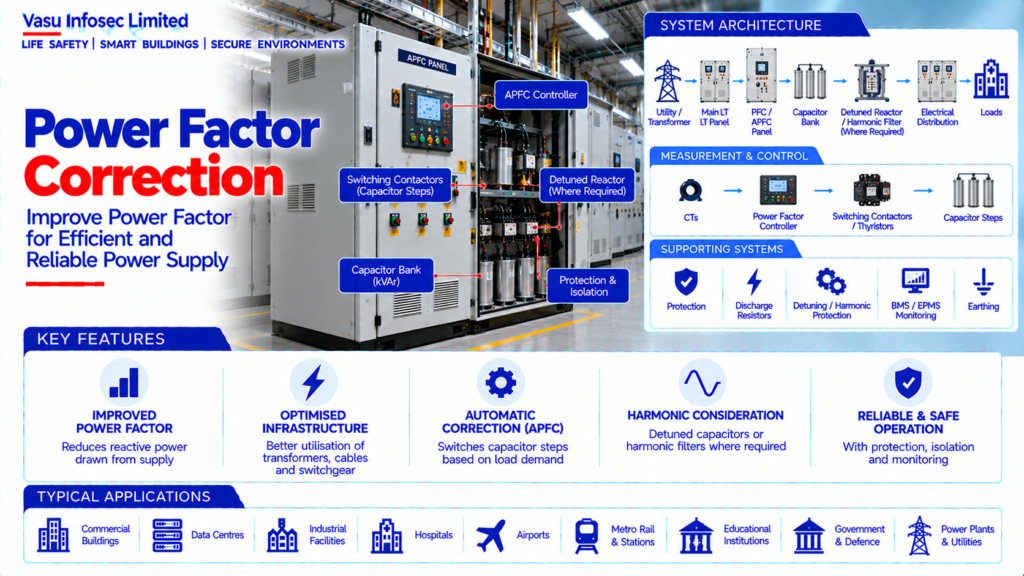
Utility / Transformer → Main LT Panel → PFC / APFC Panel → Capacitor Banks / Detuned Reactors / Harmonic Filter → Electrical Distribution → Loads
Measurement → CTs → PF Controller → Switching Contactors / Thyristors → Capacitor Steps
Supporting Systems → Protection → Discharge Resistors → Detuning / Harmonic Protection → BMS / EPMS Monitoring, where applicable
3. Power Factor Fundamentals
Power factor represents the relationship between useful active power and apparent power. For sinusoidal systems, it is commonly expressed as the cosine of the phase angle between voltage and current. In practical installations, distortion caused by nonlinear loads also affects total power factor.
4. Causes of Low Power Factor
Low power factor may result from inductive loads such as motors, transformers and certain magnetic devices. Harmonic-producing nonlinear loads can additionally introduce current distortion and require specialised correction measures.
5. Active, Reactive & Apparent Power
Active power is measured in kW, reactive power in kVAr and apparent power in kVA. The relationship among these quantities is fundamental to PFC sizing and electrical system assessment.
6. Power Factor Correction Objective
The objective is to achieve the required operating power factor without creating excessive capacitive conditions, resonance or unacceptable harmonic interaction. The target power factor should be established from the facility and utility requirements.
7. Capacitor Bank PFC
Capacitor banks provide leading reactive power that offsets part of the lagging reactive power drawn by inductive loads. The capacitor capacity is normally expressed in kVAr.
8. Fixed Capacitor Bank
A fixed capacitor bank provides a constant amount of reactive compensation. It may be suitable for loads with relatively stable operating conditions but can cause overcorrection when the load varies significantly.
9. Automatic Power Factor Correction
An APFC panel automatically switches capacitor stages according to measured power factor and reactive demand. This allows the correction level to follow changing facility loads.
10. APFC Controller
The APFC controller receives voltage and current measurements, calculates the operating power factor and determines which capacitor stages should be connected or disconnected according to the programmed control strategy.
11. Capacitor Switching
Capacitor stages may be switched using contactors or fast electronic switching devices depending on the application. Switching sequence, step size and operating frequency should be selected to minimise hunting and excessive switching.
12. Capacitor Step Selection
The total PFC capacity is divided into steps so that the controller can achieve an appropriate correction level over the expected load range. Step sizes should be selected from the facility’s reactive-load profile.
13. PFC Sizing Principle
A common sizing relationship for a target power factor is:
Qc = P × (tan φ₁ − tan φ₂)
where P is active power, φ₁ corresponds to the initial power factor and φ₂ corresponds to the target power factor. Final selection should consider actual load variation, harmonics and manufacturer data.
14. Load Profile Assessment
PFC should be sized from actual or expected operating load rather than only connected load. Minimum, average and peak operating conditions should be reviewed to prevent under-correction or overcorrection.
15. Harmonics & Capacitor Banks
Capacitors can interact with system inductance and harmonic currents. Harmonic assessment is therefore important before installing conventional capacitor banks in facilities containing large numbers of nonlinear loads.
16. Detuned Capacitor Banks
Detuned PFC systems use reactors in series with capacitor stages to shift the system’s resonance characteristics and reduce the risk of undesirable harmonic amplification. Reactor tuning should be selected according to the harmonic environment and approved design.
17. Harmonic Filters
Where harmonic distortion is significant, passive filters, active harmonic filters or other approved power-quality solutions may be required instead of or in addition to conventional capacitors.
18. Resonance Consideration
The combination of system inductance and capacitor banks can create resonant conditions. The PFC design should evaluate the transformer, cable, busbar and capacitor characteristics together with expected harmonic orders.
19. Capacitor Protection
PFC panels should include appropriate protection against overcurrent, short circuit and abnormal operating conditions. Capacitor discharge arrangements should be provided as required by the selected equipment.
20. Capacitor Discharge
Capacitors retain electrical charge after disconnection. Suitable discharge resistors or approved discharge mechanisms should reduce residual voltage to the required safe level within the specified time.
21. PFC Panel Architecture
A typical APFC panel includes incomer protection, capacitor contactors / switching devices, capacitor banks, reactors where required, APFC controller, CT input, protection, indication, ventilation and monitoring.
22. CT Placement
The current transformer used by the APFC controller should be positioned and oriented so that the controller measures the facility load correctly. CT ratio and polarity should be verified during commissioning.
23. Generator Operation
Capacitor banks should be coordinated with DG operation. Switching large capacitor banks can affect generator voltage regulation and transient behaviour, so the PFC strategy should be compatible with the generator operating philosophy.
24. UPS & Critical Loads
PFC should be coordinated with UPS systems and other power-electronic equipment. UPS input characteristics, harmonics and power-factor behaviour should be considered before applying capacitor-based correction.
25. Installation Requirements
Installation should verify:
- Correct PFC capacity
- Correct APFC controller
- Correct capacitor step arrangement
- Correct CT ratio and polarity
- Correct capacitor voltage rating
- Correct reactor / detuning arrangement
- Correct protection
- Correct ventilation
- Correct discharge arrangement
- Correct harmonic mitigation
- Correct BMS / EPMS interface
- Proper identification and cable routing
26. Testing & Commissioning
PFC commissioning should verify:
- Initial power factor
- Capacitor step operation
- APFC controller operation
- CT polarity and measurement
- Target power factor
- Capacitor current
- Voltage and frequency
- Harmonic conditions where required
- Protection operation
- Generator interaction where applicable
- Alarm and monitoring functions
27. Maintenance
Maintenance should include capacitor inspection, terminal checks, reactor inspection where applicable, controller operation, contactor / switching-device condition, cooling, protection, harmonic review and measurement of operating power factor.
28. Failure & Recovery
The system should be assessed for capacitor failure, step-switching failure, controller failure, blown protection, overheating, excessive harmonics and abnormal power factor. Failed capacitor stages should be isolated and replaced through controlled maintenance.
29. Design Change Control
Changes to transformer capacity, major motors, UPS systems, VFDs, nonlinear loads, harmonic-producing equipment or generator operation should trigger a review of the PFC and harmonic strategy.
30. Documentation
Power factor correction documentation should include, as applicable:
- Load profile
- Initial and target power factor
- PFC sizing calculation
- APFC panel schedule
- Capacitor bank schedule
- Reactor / detuning details
- Harmonic assessment
- Protection details
- CT details
- Control schematic
- Testing and commissioning records
- Power-quality measurements
- As-built drawings
- O&M manual
31. Engineering Objective
The engineering objective is:
Assess Load & Power Factor → Determine Reactive Power Requirement → Establish Target PF → Size Capacitor / PFC System → Assess Harmonics & Resonance → Select Fixed / APFC / Detuned / Filtered Solution → Integrate Protection & Monitoring → Test Operating Conditions → Establish Stable, Efficient & Utility-Compliant Power Factor
Frequently Asked Questions
What is the purpose of power factor correction?
To achieve the required operating power factor while avoiding excessive capacitive conditions, resonance or unacceptable harmonic interaction.
When should harmonics be assessed?
Harmonics should be assessed before conventional capacitor banks are installed where nonlinear loads may produce significant distortion.
What is the common PFC sizing relationship shown in this resource?
Qc = P × (tan φ₁ − tan φ₂), with P as active power and φ₁ and φ₂ representing initial and target power-factor angles.
SEO & Publishing Details
| Field | Suggested website content |
| SEO title | Power Factor Correction | Electrical Engineering Guide |
| Meta description | Understand power factor correction, including system architecture, key components, design considerations, installation, testing, maintenance and documentat |
| Primary keyword | power factor correction |
| Secondary keywords | power factor correction architecture, power factor correction design, power factor correction sizing, power factor correction testing, electrical and power systems |
| Suggested URL slug | power-factor-correction |
| Suggested image alt text | Illustration of power factor correction architecture and main components |