
Article
RS-485 Communication Fundamentals
Oct 2026
Direct Answer
RS-485 is a differential serial communication standard used to connect controllers, meters, sensors, actuators and other field devices in building automation and ELV systems. It supports multi-device communication for protocols such as Modbus RTU and BACnet MS/TP. Reliable implementation depends on suitable bus topology, compatible communication parameters, correct addressing, cable selection, termination and manufacturer-approved installation practices.
1. Engineering Overview
RS-485 is a differential serial communication standard widely used for connecting controllers, meters, sensors, actuators and other field devices in building automation and ELV systems. It provides a practical multi-device communication medium for protocols such as Modbus RTU and BACnet MS/TP.
2. Communication Architecture
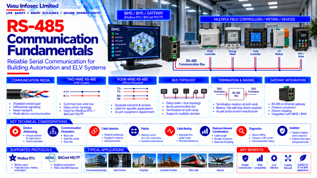
IBMS / BMS / Gateway → RS-485 Communication Bus → Multiple Field Controllers / Meters / Devices
Typical Applications → Modbus RTU → BACnet MS/TP → Metering → HVAC Controllers → Energy Monitoring → Other Approved Field Interfaces
3. Differential Signalling
RS-485 transmits information using differential signalling over a balanced pair. The receiving device determines the signal based on the voltage difference between the communication conductors, providing improved resistance to electrical noise compared with single-ended signalling.
4. Two-Wire RS-485
Two-wire RS-485 is commonly implemented as a half-duplex bus. Devices share the same communication pair and transmit according to the protocol’s communication-control mechanism.
5. Four-Wire RS-485
Four-wire implementations may be used where separate transmit and receive pairs are required by the application. The final arrangement should follow the selected protocol and equipment manufacturer’s requirements.
6. Bus Topology
RS-485 should generally be implemented as a controlled bus / daisy-chain arrangement. Long uncontrolled star connections can create reflections and communication instability and should be avoided unless specifically supported by the approved design.
7. Device Addressing
Devices connected to the same RS-485 communication segment should have unique addresses as required by the selected protocol. Duplicate addresses can result in communication conflicts and unreliable data exchange.
8. Communication Parameters
Typical serial parameters include baud rate, data bits, parity and stop bits. All devices on the same communication segment should use compatible parameters as defined by the protocol and approved equipment documentation.
9. Cable Selection
A suitable shielded twisted-pair communication cable should be selected according to the protocol, distance, environment and manufacturer requirements. Cable characteristics should support the required impedance and noise performance.
10. Polarity
The differential communication conductors should be connected consistently across the network. Incorrect polarity can prevent communication or cause unstable operation depending on the connected devices.
11. Termination
Termination resistors may be required at the appropriate ends of the RS-485 bus to reduce signal reflections. Termination should follow the selected protocol and equipment manufacturer’s requirements.
12. Biasing / Fail-Safe Bias
Where required, biasing or fail-safe bias arrangements may be provided to establish a defined idle-state condition. The design should avoid conflicting bias networks between multiple devices.
13. Cable Shielding & Earthing
Shielding may be used to reduce electromagnetic interference. Shield termination and earthing should follow the approved electrical / ELV design and manufacturer recommendations to avoid unwanted ground-current paths.
14. Cable Routing
RS-485 communication cables should be routed with appropriate segregation from high-voltage power cables, motors and other significant sources of electromagnetic interference. Crossings should be arranged according to the approved installation practice.
15. Maximum Network Considerations
The permissible cable length, number of connected devices, baud rate and network loading depend on the RS-485 implementation and selected protocol. The final design should remain within the limits specified by the applicable equipment and protocol.
16. Repeaters & Network Segmentation
RS-485 repeaters or isolated interfaces may be used where required to extend communication distance, increase device capacity or separate network segments. Each segment should remain within its approved electrical and communication limits.
17. Isolation
Galvanic isolation may be used where required to protect communication equipment from potential differences, electrical noise or ground-loop conditions. Isolation requirements should be established during detailed design.
18. Gateway Integration
RS-485 devices may connect to Ethernet-based IBMS networks through protocol gateways or serial communication servers. The gateway should correctly map device addresses, registers / objects, data types, units and status information.
19. Communication Diagnostics
Diagnostics should identify communication timeout, device offline condition, invalid response, framing errors, CRC errors, addressing conflicts and other applicable faults. Diagnostic information should support systematic troubleshooting.
20. Installation Requirements
Installation should verify:
- Correct RS-485 cable
- Correct bus topology
- Correct polarity
- Correct device addresses
- Correct baud rate
- Correct parity and stop bits
- Correct termination
- Correct biasing, where required
- Correct shielding / earthing
- Proper cable segregation
- Correct gateway configuration
21. Testing & Commissioning
RS-485 commissioning should verify:
- Physical continuity
- Polarity
- Communication parameters
- Device addressing
- Device communication
- Register / object values
- Data integrity
- Termination
- Gateway communication
- Communication failure indication
- IBMS point mapping
22. Troubleshooting
Typical RS-485 problems include incorrect polarity, duplicate device addresses, incompatible baud rate, incorrect parity, excessive cable length, poor termination, incorrect topology, electromagnetic interference, inadequate shielding, loose connections and gateway configuration errors.
23. Maintenance
Maintenance should include cable and termination inspection, communication diagnostics, device status checks, gateway verification, configuration backup and periodic validation of critical communication points.
24. Design Change Control
Changes to RS-485 devices, addresses, communication parameters, cable routes, topology, termination, gateways or connected protocols should be reviewed against the approved communication architecture before implementation.
25. Documentation
RS-485 documentation should include, as applicable:
- RS-485 network architecture
- Device schedule
- Address schedule
- Communication parameter schedule
- Cable schedule
- Network topology
- Termination arrangement
- Gateway details
- Point / register mapping
- Testing and commissioning records
- As-built drawings
- O&M manual
26. Engineering Objective
The engineering objective is:
Correct RS-485 Design → Proper Bus Topology → Correct Addressing & Parameters → Reliable Differential Communication → Controlled Termination & Shielding → Accurate Gateway Integration → Verified Data Exchange → Complete Testing → Maintainable Field Communication Network
Frequently Asked Questions
What is RS-485 used for in building automation?
It provides a differential serial communication medium for connecting compatible controllers, meters, sensors and other field devices, including systems using Modbus RTU or BACnet MS/TP.
What is the difference between two-wire and four-wire RS-485?
Two-wire RS-485 is commonly used as a half-duplex bus with devices sharing a communication pair. Four-wire implementations may use separate transmit and receive pairs where the application and equipment support them.
Why is a bus or daisy-chain topology generally preferred?
A controlled bus topology helps limit reflections and communication instability. Long uncontrolled star connections should be avoided unless specifically supported by the approved design.
Do all devices on an RS-485 segment need the same serial settings?
Devices on the same segment need compatible settings, including baud rate, data bits, parity and stop bits, as specified by the protocol and approved equipment documentation.
Where should RS-485 termination be installed?
Termination may be required at the appropriate ends of the bus. The exact arrangement must follow the selected protocol and equipment manufacturer’s requirements.
What should be checked when RS-485 communication fails?
Check polarity, addressing, serial parameters, cable length, topology, termination, shielding, loose connections, electromagnetic interference and gateway configuration.
SEO & Publishing Metadata
| SEO title | RS-485 Communication Fundamentals for IBMS & Building Automation |
| Meta description | Learn RS-485 communication fundamentals for ELV and IBMS, including bus topology, addressing, serial settings, cabling, termination, troubleshooting and commissioning. |
| Suggested URL slug | /rs-485-communication-fundamentals/ |
| Primary keyword | RS-485 communication |
| Secondary keywords | RS-485 for IBMS, RS-485 bus topology, Modbus RTU, BACnet MS/TP, RS-485 termination, RS-485 troubleshooting |
| Suggested image alt text | RS-485 serial communication bus connecting multiple field controllers and meters to an IBMS gateway |