
Article
Tunnel Cause & Effect Matrix
Oct 2026
Direct Answer
A tunnel cause-and-effect matrix defines the relationship between fire, fault and emergency inputs and the corresponding automatic, supervisory and operator-controlled outputs across tunnel life-safety systems.
1. Engineering Overview
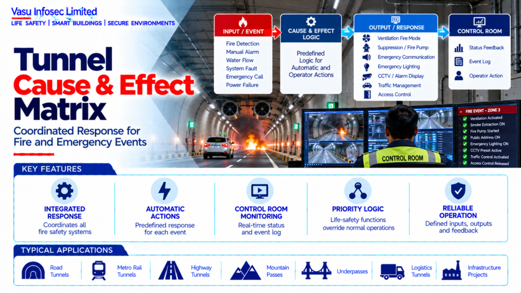
A Tunnel Cause & Effect (C&E) Matrix defines the relationship between fire, fault and emergency inputs and the corresponding automatic, supervisory and operator-controlled outputs. It is the principal functional document for coordinating fire detection, alarm, ventilation, suppression, emergency communication, CCTV, emergency lighting, traffic management and control-room response.
2. Complete Cause & Effect Architecture
Input / Event → Signal Processing → Cause & Effect Logic → Output Command → Equipment Response → Status Feedback → Control Room / Event Log
Typical Inputs → Fire Detection / Manual Alarm / Emergency Call / Water Flow / System Fault / Power Failure
Typical Outputs → Fire Alarm → Ventilation Fire Mode → Smoke Extraction → Suppression → Fire Pump → CCTV Preset / Display → Emergency Communication → Emergency Lighting → Traffic / Access Control
3. C&E Philosophy
The matrix should define every safety-critical input, initiating condition, output command, time delay where applicable, priority, reset condition, feedback signal and operator action. Each sequence should be traceable to the approved fire-safety and emergency operating philosophy.
4. Input Classification
Inputs may include automatic fire detection, manual fire alarm, water-flow signals, pump status, equipment faults, emergency telephone activation, power failure, ventilation status and other approved emergency signals. Each input should have a unique identification and defined source.
5. Fire Detection Input
A confirmed fire-detection signal should initiate the outputs defined for the affected tunnel zone. The matrix should identify the zone, associated ventilation response, alarm response, CCTV response and other required actions.
6. Manual Fire Alarm Input
Manual fire alarm activation should initiate the approved emergency sequence for the relevant zone or tunnel section. The response should be consistent with the fire detection philosophy unless a different sequence is specifically approved.
7. Fire Alarm Output
Fire alarm outputs may include local alarm indication, control-room alarm, public-address activation, event logging and commands to other fire-safety systems. The exact output should be defined for each initiating event.
8. Ventilation Fire-Mode Output
Fire events may command jet fans, smoke-extraction fans, supply fans, exhaust fans and dampers according to the fire location and approved smoke-control strategy. Normal ventilation commands should be overridden where required.
9. Smoke Extraction Output
Where dedicated smoke extraction is provided, the C&E matrix should identify the extraction zone, fan start command, damper position and feedback expected for each fire scenario.
10. Fire Pump Output
Where a fire-water demand is initiated or monitored through the integrated system, the matrix should define pump-start, pump-running, pump-fault and associated status indications as applicable to the approved fire-pump control philosophy.
11. Suppression Output
Sprinkler or water-mist release commands, zone-valve operation, flow monitoring and alarm indications should be defined where automatic suppression is part of the tunnel strategy.
12. CCTV Output
Fire events should identify the relevant CCTV cameras or viewing presets where integrated. The matrix should define whether camera selection, recording, alarm pop-up or other monitoring action is initiated.
13. Emergency Communication Output
The matrix should define the public-address announcement, emergency message, help-point response or responder communication action associated with each relevant emergency input.
14. Emergency Lighting Output
Where automatic emergency-lighting control is integrated, the matrix should define the activation condition, affected zones and expected system response.
15. Traffic Management Output
Fire events may initiate tunnel-entry restrictions, lane controls, variable-message signs, barriers or other traffic-management functions. The sequence should be coordinated with the approved tunnel operating procedure.
16. Access Control Output
Where access control is integrated, emergency events may release or control designated doors, gates or responder access points. Life-safety functions should take priority over routine access-control logic.
17. Control Room Indication
The control room should display the initiating event, affected zone, output status, equipment feedback and relevant faults. Operators should be able to identify incomplete or failed automatic actions.
18. Priority Logic
Life-safety outputs should have defined priority over normal operational commands. Conflicting commands between normal ventilation, traffic management, access control and fire mode should be resolved through the approved priority hierarchy.
19. Time Delays
Any intentional time delay should be explicitly identified with its purpose, duration and initiating condition. Safety-critical actions should not be unnecessarily delayed.
20. Cause & Effect Reset
The matrix should define reset conditions for alarms, ventilation, suppression, communication, traffic controls and other outputs. Reset should only occur when the initiating condition has been cleared and the approved procedure permits reset.
21. Feedback & Confirmation
Critical outputs should provide status feedback where required. Examples include fan running / fault, damper open / closed, pump running / fault, valve position and communication-system status.
22. Fault Conditions
Equipment faults should be separately identified from fire alarms. The matrix should define fault indication, control-room notification and any required degraded-mode or fail-safe response.
23. Power Failure Logic
Loss of normal power should initiate the approved emergency-power sequence and associated equipment status indications. The matrix should identify equipment expected to remain operational on emergency power.
24. Communication Failure Logic
Loss of communication between field devices, controllers and the control room should generate a fault indication and, where required, a predefined degraded operating response.
25. Manual Override
The C&E philosophy should identify authorised manual overrides and their priority relative to automatic commands. Manual actions should be controlled and recorded where required.
26. Zone-Based Logic
C&E sequences should be zone-specific wherever different tunnel sections require different ventilation, suppression, CCTV, communication or traffic responses. Zone mapping should be consistent across all systems.
27. Installation Requirements
C&E implementation should verify:
- Unique input identification
- Correct zone mapping
- Correct output allocation
- Correct priority hierarchy
- Correct time delays
- Correct reset logic
- Correct status feedback
- Correct fault monitoring
- Correct emergency-power logic
- Correct manual override
- Correct control-room indication
- Proper event logging
28. Testing & Commissioning
C&E commissioning should verify:
- Every fire-detection input
- Manual alarm inputs
- Alarm outputs
- Ventilation commands
- Smoke-extraction commands
- Suppression commands
- Fire-pump response
- CCTV selection / recording
- Emergency communication
- Emergency lighting
- Traffic-management response
- Access-control response
- Feedback signals
- Fault indications
- Reset and recovery logic
29. Integrated Scenario Testing
Representative tunnel fire scenarios should be tested from initiating input through every defined output. Tests should confirm sequence, priority, timing, feedback, operator indication and recovery. Test results should be documented against the approved C&E matrix.
30. Maintenance & Change Control
The C&E matrix should be reviewed whenever fire detection, ventilation, suppression, CCTV, communication, traffic management, access control or emergency-power arrangements are modified. Programming changes should be controlled and documented.
31. Documentation
Cause-and-effect documentation should include, as applicable:
- Master C&E matrix
- Input schedule
- Output schedule
- Zone schedule
- Cause / initiating-event descriptions
- Output command descriptions
- Time-delay schedule
- Priority hierarchy
- Reset philosophy
- Feedback schedule
- Interface matrix
- Control logic diagrams
- Testing and commissioning records
- Cause-and-effect test sheets
- Approved software / configuration records
- As-built matrix
- O&M manual
32. Engineering Objective
The engineering objective is:
Identify All Emergency Inputs → Define Zone & Event Logic → Establish Priority & Timing → Assign Required Outputs → Integrate Fire Alarm, Ventilation, Suppression, CCTV, Communication, Lighting & Traffic Systems → Provide Status Feedback & Fault Monitoring → Verify Automatic & Manual Sequences → Test Representative Fire Scenarios → Maintain a Controlled & Traceable Cause-and-Effect Configuration
Frequently Asked Questions
What is a tunnel cause-and-effect matrix?
The answer depends on the approved tunnel fire-safety strategy, project design basis and specific system configuration. Refer to the relevant technical sections; do not infer project-specific values where they are not stated.
What information should each sequence define?
The answer depends on the approved tunnel fire-safety strategy, project design basis and specific system configuration. Refer to the relevant technical sections; do not infer project-specific values where they are not stated.
How should cause-and-effect logic be tested?
The answer depends on the approved tunnel fire-safety strategy, project design basis and specific system configuration. Refer to the relevant technical sections; do not infer project-specific values where they are not stated.
SEO & Publishing Details
| SEO title | Tunnel Cause & Effect Matrix | Vasu Infosec Limited |
| Meta description | A tunnel cause-and-effect matrix defines the relationship between fire, fault and emergency inputs and the corresponding automatic, supervisory and operator-controlled outputs across tunnel life-safety systems. |
| Primary keyword | tunnel cause and effect matrix |
| Secondary keywords | fire alarm cause and effect, tunnel fire mode sequence, tunnel life safety interfaces, cause and effect testing |
| Suggested URL slug | tunnel-cause-effect-matrix |
| Suggested image alt text | Technical architecture and process flow for tunnel cause & effect matrix. |