
Article
Tunnel Fire Alarm Architecture
Oct 2026
Direct Answer
Tunnel fire alarm architecture receives detection signals, processes alarms and faults, provides annunciation and initiates approved emergency actions through defined cause-and-effect logic.
1. Engineering Overview
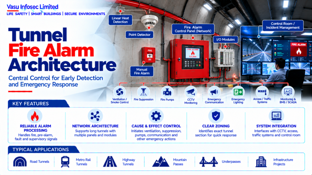
A Tunnel Fire Alarm System is the central life-safety control architecture that receives fire detection signals, processes alarms and faults, provides local and remote annunciation, and initiates approved emergency actions through defined cause-and-effect logic. It forms the interface between fire detection and other tunnel fire-safety systems.
2. Complete Tunnel Fire Alarm Architecture
Fire Detection Devices → Fire Alarm Control Panel / Network → Alarm Processing → Cause & Effect → Tunnel Emergency Systems
Detection Inputs → Linear Heat Detection / Point Detection / Other Approved Detection → Fire Alarm Panel → Control Room / Incident Management
Interfaces → Ventilation / Smoke Control → Fire Suppression → Fire Pumps → CCTV → Emergency Communication → Emergency Lighting → Access / Traffic Systems → Monitoring
3. Fire Alarm Philosophy
The fire alarm philosophy should define detection zones, alarm levels, fault monitoring, notification, control outputs, network architecture, redundancy, emergency power, operator interfaces and the required sequence of operation.
4. Fire Alarm Control Panel
The fire alarm control panel receives signals from connected detection devices and modules, identifies alarm and fault conditions, activates notification and issues approved control outputs. Panel capacity, environmental rating and network capability should match the tunnel installation.
5. Fire Alarm Network
For long tunnels or distributed facilities, multiple fire alarm panels, remote annunciators and input / output modules may be networked. The network should provide reliable communication, fault supervision and clear identification of the affected tunnel zone.
6. Detection Input Architecture
The system may receive inputs from linear heat detection, point detectors, manual fire alarm devices and other approved fire detection technologies. Each input should be mapped to the correct alarm zone and cause-and-effect response.
7. Alarm Zoning
Tunnel fire alarm zones should correspond with logical physical sections of the tunnel. Zone boundaries should support rapid incident identification and appropriate control of ventilation, suppression and emergency response systems.
8. Alarm Processing
The fire alarm system should distinguish fire alarm, pre-alarm where applicable, fault, supervisory and communication conditions. Processing logic should provide reliable alarm recognition without unnecessary delay to safety-critical actions.
9. Alarm Annunciation
Alarm information should be clearly displayed at the local fire alarm panel and, where required, at the tunnel control room. The display should identify the affected zone, device or location to the extent supported by the system.
10. Audible & Visual Notification
Where required, fire alarm notification may include sounders, hooters, strobes, beacons or public-address interfaces. Notification arrangements should account for tunnel noise, traffic conditions and emergency communication requirements.
11. Cause & Effect Architecture
The cause-and-effect matrix defines the actions initiated by each fire alarm input. Typical responses may include alarm annunciation, ventilation fire mode, smoke control, suppression release, fire pump operation, CCTV selection, emergency communication and other approved emergency actions.
12. Ventilation Interface
Fire alarm signals may initiate the approved emergency ventilation sequence. Fan start / stop, damper positions, operating mode and control priorities should be established in coordination with the tunnel ventilation design.
13. Smoke Control Interface
Where dedicated smoke extraction is provided, the fire alarm system should initiate the approved extraction sequence. The response should be coordinated with fire location, airflow direction and evacuation strategy.
14. Fire Suppression Interface
Where water mist, sprinkler or another suppression system is provided, fire alarm outputs may initiate or supervise the suppression sequence. Detection and suppression zones should be coordinated to avoid unintended discharge.
15. Fire Pump Interface
Fire alarm and fire-fighting pump systems may exchange status and alarm signals. Pump running, fault, power failure and other designated statuses should be monitored as defined by the approved interface matrix.
16. CCTV Interface
A fire alarm event may trigger CCTV camera selection or incident display at the control room. Camera mapping should be linked to fire alarm zones or detection locations where the integration is provided.
17. Emergency Communication Interface
Fire alarm events may initiate operator alerts, public-address messages or other emergency communication actions. The exact sequence should follow the approved cause-and-effect matrix.
18. Emergency Lighting Interface
Where integrated, fire alarm or emergency signals may initiate designated emergency lighting or evacuation lighting responses. The interface should be coordinated with the emergency-power architecture.
19. Traffic / Access Interface
Where specified, tunnel fire alarm events may interface with traffic management, access control, barriers, signs or other operational systems to support incident response. Safety-critical commands should follow the approved tunnel operating philosophy.
20. Control Room Architecture
The tunnel control room should provide central visibility of fire alarms, faults, zone information and relevant connected system statuses. Operator interfaces should support rapid incident verification and response.
21. Emergency Power
Fire alarm panels, network equipment, detection devices and required interfaces should be supplied from the approved fire-safety power arrangement. Standby battery capacity should support the specified monitoring and alarm duration.
22. Fault Monitoring
The fire alarm system should supervise relevant faults including power failure, battery fault, detector circuit fault, communication failure, panel fault and input / output module faults.
23. Redundancy & Availability
Critical tunnel fire alarm architecture should provide the level of availability and resilience required by the approved fire-safety philosophy. Network paths, power supplies and critical controllers should be assessed for single points of failure.
24. Installation Requirements
Installation should verify:
- Correct fire alarm panel capacity
- Correct detection zoning
- Correct device addressing / identification
- Correct network architecture
- Correct emergency power
- Correct alarm notification
- Correct cause-and-effect programming
- Correct ventilation / smoke-control interface
- Correct suppression / fire-pump interface
- Correct CCTV interface
- Correct emergency communication interface
- Proper identification and accessibility
25. Testing & Commissioning
Fire alarm commissioning should verify:
- All detection inputs
- Alarm zoning
- Panel operation
- Network communication
- Audible / visual notification
- Fault monitoring
- Cause-and-effect logic
- Ventilation / smoke-control interface
- Suppression interface
- Fire pump status interface
- CCTV interface
- Emergency communication interface
- Emergency lighting interface where provided
- Control-room indications
- Standby power operation
26. Integrated Fire Scenario Testing
Representative tunnel fire scenarios should be simulated to verify the complete alarm sequence. Testing should confirm detection, alarm annunciation, cause-and-effect actions, ventilation response, suppression response and control-room monitoring.
27. Maintenance
Maintenance should include panel inspection, battery testing, device testing, network health checks, input / output module checks, alarm-history review, fault-history review and verification of cause-and-effect functions.
28. Failure & Recovery
The system should be assessed for panel failure, network failure, power failure, battery degradation, detection-loop faults, module failure and communication loss. Faults should be clearly indicated and corrected through controlled maintenance.
29. Design Change Control
Changes to tunnel geometry, fire detection, ventilation, suppression, CCTV, emergency communication, traffic systems or control-room architecture should trigger a review of the fire alarm configuration and cause-and-effect matrix.
30. Documentation
Tunnel fire alarm documentation should include, as applicable:
- Fire alarm philosophy
- System architecture
- Panel schedule
- Detection zone schedule
- Device schedule
- Network architecture
- Input / output schedule
- Cause-and-effect matrix
- Interface matrix
- Battery calculation
- Alarm notification details
- Testing and commissioning records
- Programming / configuration records
- Alarm and fault history
- Maintenance schedule
- As-built drawings
- O&M manual
31. Engineering Objective
The engineering objective is:
Establish Tunnel Fire Alarm Philosophy → Define Detection Zones → Select & Network Fire Alarm Control Equipment → Process Fire & Fault Signals → Execute Cause & Effect → Integrate Ventilation, Suppression, Fire Pumps, CCTV & Emergency Systems → Verify Emergency Power & Fault Supervision → Test Integrated Fire Scenarios → Maintain Reliable Tunnel Fire Alarm Availability
Frequently Asked Questions
What is tunnel fire alarm architecture?
The answer depends on the approved tunnel fire-safety strategy, project design basis and specific system configuration. Refer to the relevant technical sections above; do not infer a project-specific value or requirement where it is not stated.
What does the cause-and-effect matrix define?
The answer depends on the approved tunnel fire-safety strategy, project design basis and specific system configuration. Refer to the relevant technical sections above; do not infer a project-specific value or requirement where it is not stated.
Which interfaces may connect to the fire alarm system?
The answer depends on the approved tunnel fire-safety strategy, project design basis and specific system configuration. Refer to the relevant technical sections above; do not infer a project-specific value or requirement where it is not stated.
SEO & Publishing Details
| SEO title | Tunnel Fire Alarm Architecture | Vasu Infosec Limited |
| Meta description | Tunnel fire alarm architecture receives detection signals, processes alarms and faults, provides annunciation and initiates approved emergency actions through defined cause-and-effect logic. |
| Primary keyword | tunnel fire alarm architecture |
| Secondary keywords | tunnel fire alarm panel, cause and effect matrix, tunnel fire alarm network, tunnel life safety systems |
| Suggested URL slug | tunnel-fire-alarm-architecture |
| Suggested image alt text | Technical architecture and process flow for tunnel fire alarm architecture. |