
Article
Tunnel Ventilation & Fire Mode
Oct 2026
Direct Answer
Tunnel ventilation supports normal environmental control and a coordinated emergency fire mode. Fire-mode fan, damper and airflow actions should follow the approved cause-and-effect matrix and smoke-control strategy.
1. Engineering Overview
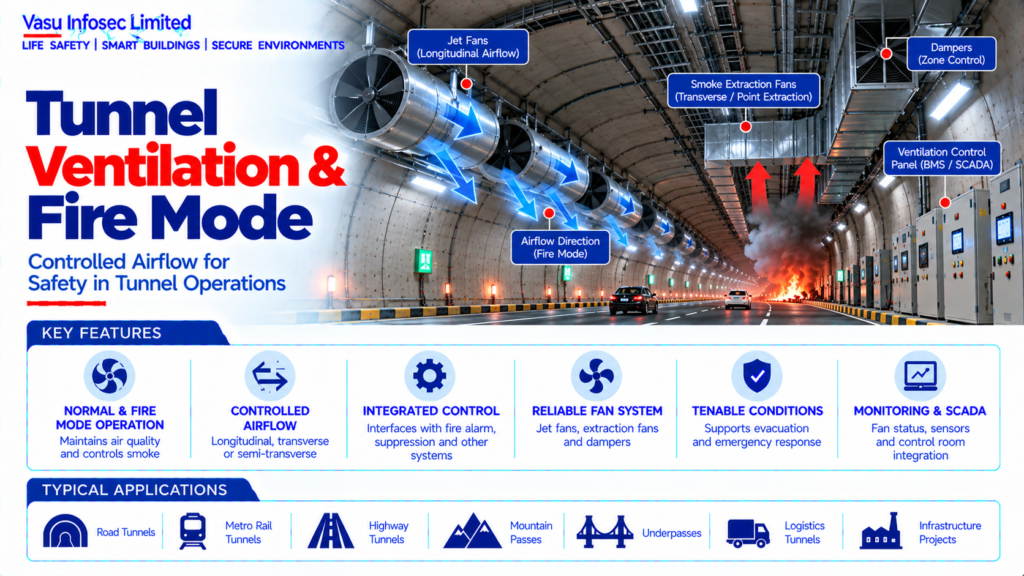
Tunnel ventilation provides environmental control during normal operation and a dedicated emergency fire mode during tunnel incidents. The fire-mode architecture is intended to control smoke movement, support evacuation and firefighting, maintain required airflow conditions and provide controlled emergency response.
2. Complete Tunnel Ventilation & Fire Mode Architecture
Normal Ventilation → Ventilation Control System → Supply / Exhaust / Jet Fans → Tunnel Airflow
Fire Detection → Fire Alarm / Control System → Fire-Mode Cause & Effect → Emergency Ventilation → Jet Fans / Smoke Extraction Fans / Dampers → Controlled Smoke Movement
Supporting Systems → Sensors → VFD / Starters → Control Panels → Emergency Power → SCADA / Control Room → CCTV / Incident Monitoring
3. Ventilation Philosophy
The ventilation philosophy should define normal operating modes, emergency fire modes, airflow direction, fan operation, smoke-control objectives, control priorities, manual override, failure response and emergency-power requirements.
4. Normal Ventilation Mode
Normal ventilation manages air quality, vehicle emissions, heat and other operational conditions. Fan operation should be controlled according to the approved ventilation strategy and monitored by the tunnel control system.
5. Fire Mode Activation
Fire mode should be initiated by the approved fire detection and tunnel incident-management strategy. The activation sequence should identify the affected zone and command the required ventilation equipment according to the approved cause-and-effect matrix.
6. Fire Location Identification
The fire location should be determined from the available detection system, CCTV verification and operator information. Fire location is critical to selecting the correct fan and airflow response.
7. Longitudinal Ventilation
Longitudinal ventilation establishes airflow along the tunnel axis. The direction and magnitude of airflow should be selected to support the approved smoke-control and evacuation strategy.
8. Critical Velocity
Where longitudinal smoke control is used, the required critical velocity should be established through the approved engineering analysis. The installed fan arrangement should demonstrate the required airflow performance.
9. Jet Fan System
Jet fans provide thrust to establish and control longitudinal airflow. Fan location, thrust, orientation, spacing and operating sequence should be determined from the approved ventilation design.
10. Smoke Extraction Mode
Where dedicated smoke extraction is provided, extraction fans and dampers should operate according to the fire location and approved smoke-control sequence. Extraction capacity should be established from the governing fire scenario.
11. Supply & Exhaust Arrangement
Supply and exhaust airflow paths should be coordinated so that the fire-mode system does not create unintended smoke movement towards evacuation routes or emergency responder access.
12. Damper Operation
Fire-mode dampers may be used to direct, isolate or control airflow and smoke extraction. Each damper should have a defined normal position, fire-mode position, fail position and status indication where required.
13. Fan Control
Fan controls may use direct starters, variable-frequency drives or other approved control arrangements. Fire-mode commands and control priorities should be clearly defined and should override normal ventilation logic where required.
14. Fan Duty & Capacity
Fan selection should consider airflow, static pressure, temperature exposure, operating duration, duty point, redundancy and environmental conditions. The selected fan should satisfy the approved smoke-control calculation.
15. Fire-Resistant Fan Performance
Fans required to operate in fire conditions should have the required temperature and duration capability established by the approved design. Supporting motors, cables, controls and mounting arrangements should be compatible with the fire-mode requirement.
16. Ventilation Sensors
Pressure, temperature, airflow, fan-status and other sensors may be used to monitor ventilation performance. Sensor selection and location should support reliable control and operational verification.
17. Fire Alarm Interface
The fire alarm system should provide the fire event and location information required to initiate the approved ventilation fire mode. Ventilation alarms and faults should be returned to the fire alarm / control system as defined.
18. Smoke Extraction Interface
Where smoke extraction is provided, the ventilation control system should coordinate fan and damper operation with the fire location and approved smoke-management sequence.
19. Fire Suppression Interface
Ventilation operation should be coordinated with hydrants, sprinklers and water mist systems where installed. The combined fire response should follow the approved cause-and-effect strategy.
20. Emergency Communication Interface
Ventilation fire mode should be coordinated with emergency communication and public-address systems so that evacuation instructions remain consistent with the smoke-control strategy.
21. CCTV & Control Room Interface
Ventilation status, fire alarms, fan operation, damper positions and relevant CCTV views should be available to the tunnel control room where integrated. Operators should be able to identify the active fire mode and system status.
22. Emergency Power
Safety-critical ventilation equipment required during fire mode should be supported by the approved emergency / standby power arrangement. Electrical capacity, source transfer, cable routing and protection should be verified.
23. Manual Override
The control philosophy should define authorised manual override of automatic fire-mode sequences. Manual intervention should be controlled, logged and consistent with the emergency operating procedures.
24. Redundancy & Availability
Critical ventilation equipment should be assessed for single points of failure. Where required, redundancy, alternative operating modes and fault-tolerant control arrangements should be incorporated.
25. Installation Requirements
Installation should verify:
- Correct fan type and duty
- Correct jet-fan arrangement where provided
- Correct smoke-extraction capacity
- Correct damper type and position
- Correct fire-mode control logic
- Correct fire alarm interface
- Correct sensor installation
- Correct emergency power
- Correct control-room monitoring
- Correct manual override
- Correct cable and equipment fire performance
- Proper identification and accessibility
26. Testing & Commissioning
Ventilation commissioning should verify:
- Fan start / stop operation
- Fan rotation and direction
- Airflow performance
- Fan status feedback
- Damper operation
- Damper position feedback
- Fire-mode activation
- Fire alarm interface
- Emergency power operation
- Control-room indications
- Fault monitoring
- Manual override
- Cause-and-effect sequence
27. Fire-Mode Performance Testing
Performance testing should verify airflow direction, fan performance, pressure conditions and smoke-control response against the approved design. Where applicable, smoke tests, airflow visualisation or other approved validation methods should be used.
28. Integrated Fire Scenario Testing
Representative fire scenarios should verify the complete sequence from fire detection through ventilation fire mode, smoke extraction, emergency communication, CCTV / control-room monitoring, suppression interfaces and evacuation support.
29. Maintenance
Maintenance should include inspection and testing of fans, motors, bearings, drives, dampers, actuators, sensors, control panels, emergency power interfaces and communication systems. Fire-mode operation should be periodically demonstrated.
30. Failure & Recovery
The system should be assessed for fan failure, damper failure, power loss, sensor failure, communication loss and incorrect airflow. Recovery procedures should define alternative ventilation modes and operator actions.
31. Design Change Control
Changes to tunnel geometry, fire detection, smoke extraction, jet-fan arrangement, ventilation controls, evacuation routes or electrical supply should trigger a review of fire-mode ventilation performance.
32. Documentation
Tunnel ventilation and fire-mode documentation should include, as applicable:
- Ventilation philosophy
- Fire-mode philosophy
- Ventilation calculations
- Smoke-control calculations / modelling
- Fan schedule
- Jet-fan schedule
- Damper schedule
- Sensor schedule
- Control philosophy
- Cause-and-effect matrix
- Interface matrix
- Emergency-power calculation
- Testing and commissioning records
- Airflow / performance test reports
- Maintenance schedule
- Emergency operating procedures
- As-built drawings
- O&M manual
33. Engineering Objective
The engineering objective is:
Establish Normal & Emergency Ventilation Philosophy → Assess Governing Fire Scenarios → Determine Airflow & Smoke-Control Requirements → Select Fans, Jet Fans, Dampers & Controls → Define Fire-Mode Sequences → Integrate Fire Detection, Alarm, Suppression & Emergency Communication → Verify Emergency Power → Test Airflow & Integrated Fire Response → Maintain Reliable Tunnel Fire-Mode Ventilation
Frequently Asked Questions
What is tunnel ventilation fire mode?
The answer depends on the approved tunnel fire-safety strategy, project design basis and specific system configuration. Refer to the relevant technical sections above; do not infer a project-specific value or requirement where it is not stated.
How is fire mode activated?
The answer depends on the approved tunnel fire-safety strategy, project design basis and specific system configuration. Refer to the relevant technical sections above; do not infer a project-specific value or requirement where it is not stated.
What should ventilation commissioning verify?
The answer depends on the approved tunnel fire-safety strategy, project design basis and specific system configuration. Refer to the relevant technical sections above; do not infer a project-specific value or requirement where it is not stated.
SEO & Publishing Details
| SEO title | Tunnel Ventilation & Fire Mode | Vasu Infosec Limited |
| Meta description | Tunnel ventilation supports normal environmental control and a coordinated emergency fire mode. Fire-mode fan, damper and airflow actions should follow the approved cause-and-effect matrix and smoke-control strategy. |
| Primary keyword | tunnel ventilation fire mode |
| Secondary keywords | tunnel jet fan system, tunnel smoke control, fire mode cause and effect, tunnel ventilation commissioning |
| Suggested URL slug | tunnel-ventilation-fire-mode |
| Suggested image alt text | Technical architecture and process flow for tunnel ventilation & fire mode. |