
Article
UPS System Architecture
Oct 2026
Direct Answer
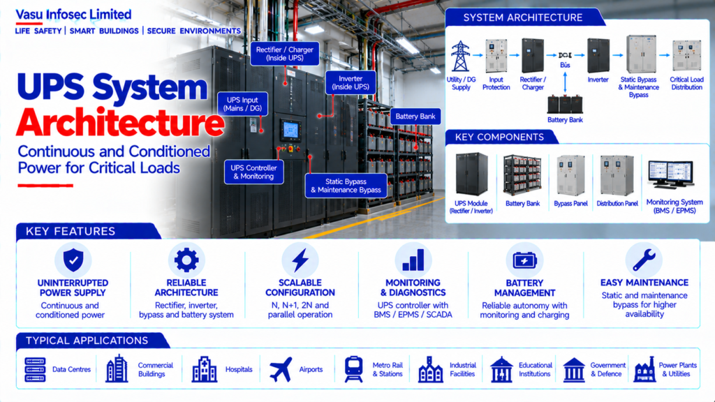
A UPS provides conditioned and uninterrupted power to designated critical loads during normal operation and source disturbances. Its architecture typically includes input protection, rectifier/charger, battery, inverter, bypass, output distribution and monitoring.
1. Engineering Overview
A UPS (Uninterruptible Power Supply) system provides continuous and conditioned electrical power to designated critical loads during normal operation, utility disturbances and source interruptions. A complete UPS architecture integrates the normal input source, rectifier / charger, energy storage, inverter, static bypass, maintenance bypass, output distribution, monitoring and associated protection.
2. Complete UPS Architecture
Utility / DG Supply → UPS Input Protection → Rectifier / Charger → DC Bus → Inverter → Static Bypass / Output → Critical Load Distribution
Battery Bank → DC Bus
Maintenance Bypass → Critical Load Bus
UPS Controller → Monitoring / BMS / EPMS / SCADA, where applicable
Supporting Systems → Input / Output Protection → Earthing → Battery Monitoring → Ventilation / Environmental Control
3. UPS Operating Modes
A UPS may operate in normal double-conversion mode, battery mode, bypass mode, maintenance-bypass mode or other manufacturer-defined modes. Each mode should have clearly defined transfer conditions and load continuity characteristics.
4. Normal Operation
During normal operation, the incoming AC supply is processed by the UPS input stage and the inverter supplies regulated power to the critical load. The battery remains connected and available to support the DC bus when required.
5. Battery Operation
When the normal input source is unavailable or outside configured limits, the UPS uses stored battery energy to maintain the inverter output. The transfer should occur without interruption to the connected critical load for a properly designed online UPS system.
6. Rectifier / Charger
The rectifier converts incoming AC power to DC and supplies the inverter DC bus. The charger function maintains the connected battery system at the required operating condition according to the UPS manufacturer’s charging philosophy.
7. Inverter
The inverter converts DC energy into regulated AC output for the critical load. It is responsible for maintaining the required output voltage, frequency and power quality within the specified operating limits.
8. Static Bypass
The static bypass provides an alternate AC path to the critical load when the inverter is unavailable, overloaded or operating outside defined conditions. Bypass operation should be coordinated with source voltage, frequency and synchronisation requirements.
9. Maintenance Bypass
A maintenance bypass provides a controlled means of isolating the UPS for maintenance while continuing to supply the critical load from the approved bypass source. The switching sequence should be designed to prevent unintended interruption.
10. Battery Bank
The battery bank stores DC energy for use during input-source failure. Battery technology, capacity, configuration, autonomy and monitoring should be selected according to the required critical-load support duration.
11. UPS Sizing
UPS capacity should be established from the critical-load schedule, power factor, load profile, starting / transient characteristics, growth allowance, redundancy philosophy and required operating margin.
12. Critical Load Classification
Only designated critical loads should be connected to the UPS unless the UPS is sized for a wider load group. Critical-load classification should be established in the approved electrical distribution and resilience philosophy.
13. Redundancy Architecture
Critical facilities may use N, N+1, 2N or other approved UPS redundancy arrangements. The selected architecture should provide the required availability and maintainability without exceeding allowable loading.
14. Parallel UPS Systems
Multiple UPS modules may operate in parallel to increase capacity or redundancy. Parallel operation requires compatible modules, load-sharing controls, synchronisation and approved system-level protection.
15. UPS Input Supply
The UPS input source may be utility, DG or another approved source. Compatibility with the upstream generator and electrical distribution system should be verified, particularly for nonlinear or rectifier-type loads.
16. UPS Output Distribution
UPS output should feed dedicated critical distribution boards or panels. Downstream protection and cable sizing should be coordinated with UPS output characteristics and available fault current.
17. Battery Monitoring
Battery monitoring may include voltage, current, temperature, state information and individual battery condition depending on the selected system. Monitoring should support preventive maintenance and early fault identification.
18. Battery Charging
Charging characteristics should be controlled according to the battery technology and manufacturer requirements. Charging current, float / boost modes and temperature compensation should be considered where applicable.
19. Generator Integration
UPS systems supplied from DG sources should be evaluated for input-current distortion, generator sizing, frequency stability, voltage regulation and step-load response. The DG and UPS operating characteristics should be compatible.
20. Power Quality
UPS systems provide regulated power to critical loads and can mitigate certain voltage and frequency disturbances. Harmonic currents, input power factor and output waveform quality should be considered in system design.
21. Protection Architecture
UPS systems should have appropriate input, output, bypass and battery protection. Protection coordination should be established with upstream and downstream electrical devices.
22. Monitoring & Integration
UPS parameters and alarms may be communicated to BMS, EPMS, SCADA or other monitoring platforms. Typical monitored information may include operating mode, input / output parameters, battery condition, bypass status and alarms.
23. Installation Requirements
Installation should verify:
- Correct UPS capacity
- Correct topology
- Correct input and output ratings
- Correct battery configuration
- Correct bypass arrangement
- Correct critical-load distribution
- Correct redundancy configuration
- Correct protection
- Correct earthing
- Correct ventilation / environmental conditions
- Correct monitoring interface
- Proper cable routing and identification
24. Testing & Commissioning
UPS commissioning should verify:
- Normal operation
- Input failure / battery operation
- Return to normal input
- Static bypass operation
- Maintenance bypass operation
- Output voltage and frequency
- Load acceptance
- Battery autonomy / discharge test as approved
- Alarm functions
- Protection operation
- Monitoring / BMS / EPMS communication
- Redundancy and module operation, where applicable
25. Maintenance
Maintenance should include inspection of UPS modules, fans, filters, terminals, batteries, bypass systems, protection devices, alarms, monitoring interfaces and environmental conditions. Battery condition and UPS event history should be reviewed periodically.
26. Failure & Recovery
The system should be assessed for utility failure, DG input disturbance, UPS module failure, battery failure, bypass failure, overload and control-system faults. Recovery procedures should be established for critical loads.
27. Design Change Control
Changes to critical-load capacity, battery autonomy, UPS modules, redundancy, bypass source, downstream distribution or generator characteristics should trigger a UPS capacity and coordination review.
28. Documentation
UPS documentation should include, as applicable:
- UPS architecture
- UPS schedule
- Critical-load schedule
- UPS sizing calculation
- Battery sizing / autonomy calculation
- Single-line diagram
- Bypass arrangement
- Protection coordination
- Monitoring / integration matrix
- Testing and commissioning records
- Battery test records
- Maintenance schedule
- As-built drawings
- O&M manual
29. Engineering Objective
The engineering objective is:
Define Critical Load Requirement → Establish UPS Capacity & Topology → Select Redundancy Philosophy → Design Rectifier, Inverter & Bypass → Size Battery Bank → Integrate Critical Distribution & Monitoring → Verify Protection & Generator Compatibility → Test All Operating Modes → Establish Reliable, Continuous & Conditioned Critical Power
Frequently Asked Questions
What are the main elements of the UPS architecture?
The source and input protection, rectifier/charger, DC bus, battery, inverter, static and maintenance bypass, critical-load distribution, monitoring and protection.
What should UPS sizing consider?
Critical-load schedule, power factor, load profile, starting/transient characteristics, growth allowance, redundancy and operating margin.
Why is generator compatibility important?
The source material identifies generator voltage/frequency stability, alternator characteristics, harmonics and transient response as factors to assess.
SEO & Publishing Details
| Field | Suggested website content |
| SEO title | UPS System Architecture | Electrical Engineering Guide |
| Meta description | Understand ups system architecture, including system architecture, key components, design considerations, installation, testing, maintenance and documentat |
| Primary keyword | ups system architecture |
| Secondary keywords | ups system architecture architecture, ups system architecture design, ups system architecture sizing, ups system architecture testing, electrical and power systems |
| Suggested URL slug | ups-system-architecture |
| Suggested image alt text | Illustration of ups system architecture architecture and main components |