
Article
Water Mist Pressure & Flow Calculation
Oct 2026
Direct Answer
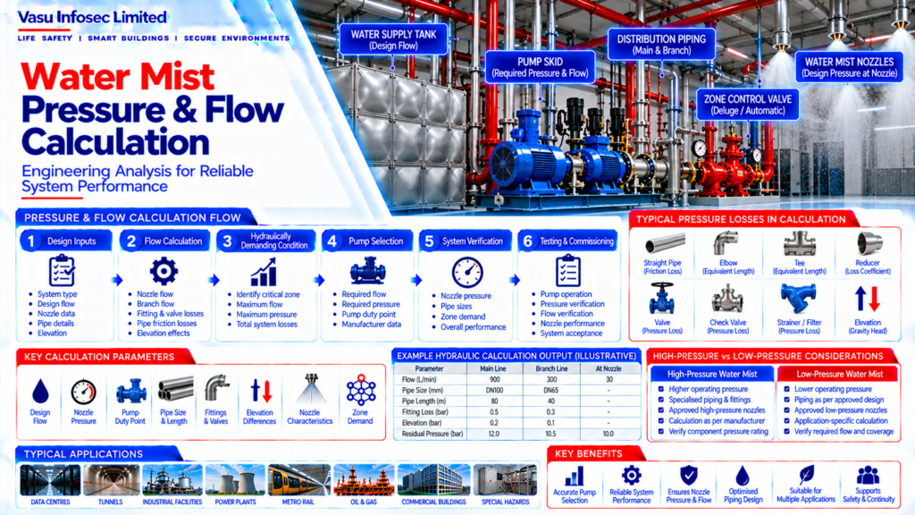
Water mist pressure and flow calculations verify whether a system can deliver the required water flow at the required pressure to the design nozzles under the approved operating condition. The calculation supports pump selection, pipe sizing, nozzle selection and performance verification. It should use verified design inputs and the selected manufacturer’s approved pressure-flow data and calculation methodology.
1. Engineering Overview
Water Mist Pressure & Flow Calculation verifies that the water mist system can deliver the required water flow at the required pressure to the designed nozzles under the approved operating condition. The calculation forms the basis for pump selection, pipe sizing, nozzle selection and confirmation of system performance.
2. Pressure & Flow Calculation Architecture
Water Source → Pump / Pressure Source → Main Piping → Zone Control Valve → Distribution Piping → Branch Piping → Nozzles → Required Pressure & Flow at Design Condition
3. Calculation Inputs
Typical calculation inputs include:
- Water mist system type
- Design flow
- Required nozzle pressure
- Pump duty point
- Water supply conditions
- Pipe material
- Pipe diameters
- Pipe lengths
- Fittings
- Valves
- Elevation differences
- Nozzle characteristics
- Number of operating nozzles
4. Design Flow Requirement
The design flow is determined from the required number of operating nozzles and their approved flow characteristics. The calculation should establish the total flow demand for the hydraulically relevant design condition.
5. Nozzle Flow Relationship
Nozzle flow is dependent on the selected nozzle characteristics and operating pressure. The manufacturer’s approved relationship between pressure and flow should be used for the selected nozzle rather than an assumed generic coefficient.
6. Pressure Requirement
The available pressure at each nozzle should be sufficient to achieve the required discharge characteristics. The calculation should account for pressure losses through piping, fittings, valves, elevation and other relevant components.
7. Pump Duty Point
The pump or pressure source should be selected to meet the required flow and pressure at the hydraulically most demanding condition. The pump duty point should be verified against the approved manufacturer’s performance data.
8. Pipe Friction Loss
Water flow through piping produces friction losses. The approved hydraulic calculation should account for pipe material, internal diameter, length, flow rate and the applicable calculation methodology.
9. Fitting & Valve Losses
Elbows, tees, reducers, control valves, check valves, strainers and other components create additional pressure losses. Relevant losses should be included in the approved calculation.
10. Elevation Effects
Changes in elevation affect available pressure within the water mist network. The actual vertical geometry of the piping should be incorporated into the calculation where applicable.
11. Branch Flow Distribution
The calculation should establish flow distribution through each branch and nozzle. The arrangement should ensure that the required pressure and flow are available at the design nozzles.
12. Hydraulically Most Demanding Condition
The hydraulically most demanding condition should be identified based on the approved system design. The calculation should demonstrate that the pump / pressure source can satisfy this condition while maintaining the required nozzle performance.
13. High-Pressure Water Mist Calculation
For high-pressure systems, the calculation should account for the selected high-pressure pump, pressure-rated piping, specialised fittings and nozzle characteristics. All components should be compatible with the design operating pressure.
14. Low-Pressure Water Mist Calculation
For low-pressure systems, the calculation should use the approved pressure regime and manufacturer methodology. Pipe sizing, pump selection and nozzle performance should be coordinated accordingly.
15. Zone Demand
Where the system is divided into zones, the calculation should establish the required flow and pressure for each applicable operating zone. The pump and distribution network should be capable of meeting the design demand.
16. Calculation Verification
The completed calculation should verify:
- Correct design flow
- Required nozzle pressure
- Pump duty point
- Pipe sizes
- Pipe lengths
- Fittings and valves
- Elevation effects
- Nozzle flow
- Zone demand
- Hydraulically demanding condition
17. Site Coordination
The installed piping network, pump skid, valves and nozzles should correspond with the approved calculation. Any change in pipe size, route, nozzle location, valve arrangement or pump configuration should be reviewed for its impact on pressure and flow.
18. Testing & Commissioning
Commissioning should verify the installed system against the approved pressure and flow design.
Checks may include:
- Pump operation
- Pressure verification
- Flow verification
- Zone valve operation
- Nozzle arrangement
- Alarm / release sequence
- Test drain operation
- Interface signals
19. Documentation
Pressure and flow calculation documentation should include, as applicable:
- Design basis
- Hydraulic calculation report
- Pump datasheet / performance curve
- Pipe and fitting schedule
- Nozzle schedule
- Zone control arrangement
- Pressure / flow test records
- Approved drawings
- Commissioning report
- As-built documentation
20. Engineering Objective
The engineering objective is:
Accurate Design Inputs → Correct Flow Demand → Verified Nozzle Pressure → Engineered Pipe Sizing → Accounted Friction & Elevation Losses → Correct Pump Duty Point → Confirmed Zone Demand → Complete Testing → Reliable Water Mist System Performance
Frequently Asked Questions
What does a water mist pressure and flow calculation verify?
It checks whether the system can provide the required flow and pressure at the design nozzles under the approved operating condition.
What information is needed for the calculation?
Inputs typically include system type, design flow, required nozzle pressure, pump duty point, water supply conditions, pipe sizes and lengths, fittings, valves, elevations, nozzle characteristics and the number of operating nozzles.
How should nozzle flow be calculated?
Use the approved pressure-flow relationship supplied by the manufacturer for the selected nozzle rather than an assumed generic coefficient.
What is the hydraulically most demanding condition?
It is the design condition identified under the approved system design that requires verification of sufficient pressure and flow at the relevant zone or nozzle arrangement.
Can changes to installed piping be made without recalculation?
Changes to pipe size, route, nozzle location, valve arrangement or pump configuration should be reviewed for their impact on pressure and flow and reflected in approved documentation where required.
SEO and Website Publishing Details
SEO title: Water Mist Pressure & Flow Calculation: Hydraulic Design Guide
Meta description: Learn how water mist pressure and flow calculations use nozzle data, pipe losses, elevations, zone demand and pump duty points to verify the approved system design.
Suggested URL slug: /engineering/water-mist-pressure-flow-calculation/
Primary keyword: water mist pressure and flow calculation
Related keywords: water mist hydraulic calculation, water mist pump duty point, nozzle pressure flow relationship, water mist pipe friction loss, water mist zone demand
Suggested internal links: Water Mist System Complete Architecture; Water Mist Pump Skid Architecture; Water Mist Nozzle Types & Applications; Water Mist Piping Network Design; Water Mist Zone Control Arrangement.