
Case Study
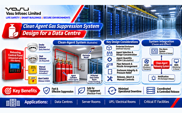
Clean Agent Gas Suppression System Design for a Data Centre
Nov 2026
Direct Engineering Answer
A clean-agent system for a data centre must be designed around the confirmed hazard, protected enclosure volume, agent-specific design concentration and the complete OEM-calculated cylinder, pipe and nozzle arrangement. The illustrative room volume in this case is 864 m³; final agent quantity and discharge design are not established by volume alone.
1. Project Background
This case study presents an illustrative engineering approach for developing a clean-agent fire suppression system for a critical data centre room. The objective is to demonstrate the engineering workflow for defining a protected enclosure, coordinating agent storage and discharge arrangements, and integrating the suppression system with detection, HVAC, pressure relief and emergency controls. This case is prepared for the engineering knowledge library and is not presented as a verified record of a specific completed project.
2. Facility / System Profile
| Parameter | Design Basis | Engineering Relevance |
| Facility | Critical data centre equipment room | Sensitive electronic equipment requires residue-free suppression. |
| Suppression | Total-flooding clean-agent system | Designed for enclosed hazards where agent concentration can be established. |
| Protected Space | Server / electrical equipment room | Enclosure integrity is essential for agent retention. |
| Detection | Addressable fire alarm / releasing system | Provides automatic detection and controlled release logic. |
| HVAC | Precision cooling | Shutdown and damper response may be required by approved cause-and-effect. |
| Integration | Fire alarm, releasing panel, HVAC, pressure relief and BMS | Requires coordinated life-safety sequence. |
3. Engineering Challenge
Clean-agent suppression design requires the agent concentration to be established for the specific fire hazard and enclosure volume. The engineer must coordinate agent selection, cylinder arrangement, pipe network, discharge nozzles, enclosure integrity, pressure relief and releasing logic. Final agent quantity and nozzle design are manufacturer-specific and should be verified using approved OEM calculation software.
- Define the protected enclosure and design volume.
- Select the clean agent and design concentration for the approved hazard.
- Determine the required agent quantity using the selected manufacturer’s methodology.
- Coordinate cylinder storage, pipe network and nozzle locations.
- Provide enclosure integrity and pressure-relief provisions.
- Coordinate detection, pre-discharge warning, release, abort and manual release functions.
4. Engineering Basis and Applicable References
The suppression engineering framework used for this library identifies NFPA 2001, applicable local fire and building requirements, and manufacturer design manuals as relevant references. NFPA 72 should be coordinated for detection and releasing-system functions where applicable. Final agent concentration, quantity, pipe sizing, nozzle selection and discharge timing shall be established from the selected agent listing/approval and OEM calculation software. No universal agent quantity is assumed.
| Reference | Engineering Application |
| NFPA 2001 | Clean-agent extinguishing system design, installation, enclosure and safety considerations where applicable. |
| NFPA 72 | Detection, releasing and notification interface where applicable. |
| NBC India Part 4 | Fire and life-safety provisions for buildings. |
| IS / Local Authority Requirements | Applicable fire protection and building requirements. |
| Manufacturer Data | Agent properties, design concentration, cylinder filling, pipe network and nozzle calculations. |
| Project Fire Strategy | Defines protected hazards, release philosophy and interfaces. |
5. Existing Conditions / Assessment Basis
- The protected data centre room is assumed to be a closed enclosure suitable for total flooding.
- Room dimensions are taken as 18 m × 12 m × 4 m for the illustrative assessment.
- The room contains electronic equipment with no significant open-flame fuel storage.
- Normal HVAC operation is continuous and the approved release sequence includes HVAC control where required.
- All openings, doors, cable penetrations and dampers are subject to enclosure-integrity assessment.
- Final agent type and concentration must be established by the approved fire strategy and selected OEM.
6. Engineering Methodology
- Confirm the hazard classification and protected enclosure.
- Determine gross enclosure volume from coordinated architectural dimensions.
- Identify permanent exclusions from the protected volume where permitted by the selected design methodology.
- Establish the design concentration from the selected clean-agent standard, listing and hazard classification.
- Determine the preliminary agent quantity using the manufacturer’s approved calculation method.
- Select cylinder arrangement and storage location.
- Develop the pipe network and nozzle layout.
- Run the OEM hydraulic/discharge calculation.
- Verify enclosure integrity and pressure relief.
- Develop the complete releasing-system cause-and-effect matrix and commissioning procedure.
7. Illustrative Protected Volume Assessment
For illustration, assume a data centre room measuring 18 m × 12 m × 4 m. The gross enclosure volume is:
V = L × W × H
V = 18 m × 12 m × 4 m = 864 m³
| Parameter | Value | Unit | Engineering Comment |
| Room Length | 18 | m | Illustrative enclosure dimension. |
| Room Width | 12 | m | Illustrative enclosure dimension. |
| Room Height | 4 | m | Illustrative clear enclosure height. |
| Gross Enclosure Volume | 864 | m³ | 18 × 12 × 4. |
| Design Concentration | OEM / hazard specific | % | Must be obtained from selected agent methodology. |
| Final Agent Quantity | OEM calculated | kg | Not determined from volume alone. |
8. Illustrative Agent Quantity Assessment
A clean-agent quantity cannot be responsibly finalised from room volume alone because the required mass depends on the selected agent, design concentration, enclosure conditions, ambient design temperature and the approved manufacturer methodology. For publication purposes, the engineering workflow is therefore shown rather than inventing a universal kg/m³ factor.
Preliminary design relationship:
Agent mass = f(volume, design concentration, agent properties, design temperature, enclosure conditions)
The final value shall be generated using the selected manufacturer’s listed calculation software or approved design procedure. The resulting cylinder quantity, fill pressure and pipe/nozzle arrangement must be checked against the same approved system.
9. Engineering Solution
- Use a listed clean-agent system suitable for the specific data-centre hazard.
- Base the protected volume on coordinated architectural dimensions and approved enclosure boundaries.
- Use OEM calculation software for final agent quantity, pipe sizing and nozzle discharge.
- Provide a supervised releasing control panel with appropriate detection and release logic.
- Provide pre-discharge warning, manual release and abort functions where required by the approved design.
- Coordinate HVAC shutdown, damper operation and pressure relief with the release sequence.
- Complete enclosure integrity testing before final acceptance.
10. Releasing Cause-and-Effect Strategy
| Initiating Condition | System Response | Verification |
| First Detector Alarm | Generate fire alarm / pre-alarm indication according to approved logic. | Detector functional test. |
| Confirmed Release Condition | Initiate approved pre-discharge sequence. | Cause-and-effect test. |
| Pre-Discharge Delay | Provide warning and controlled release countdown where designed. | Timer/notification test. |
| Manual Release | Initiate approved release sequence subject to system design. | Manual release test. |
| Abort | Suspend/cancel release as permitted by the approved system logic. | Abort test. |
| HVAC Interface | Execute approved shutdown/damper sequence. | Integrated HVAC test. |
| Agent Discharge | Discharge clean agent through calculated nozzle network. | OEM commissioning procedure. |
| Post-Discharge | Provide alarm/status indication and controlled reset/recovery. | Functional test. |
11. Enclosure Integrity and Pressure Relief
The clean-agent system depends on the protected enclosure retaining the agent for the required design period. Doors, cable penetrations, ducts, dampers, raised floors and other openings therefore require review. Pressure relief provisions must also be coordinated because rapid agent discharge can create transient pressure changes.
- Verify permanent and normally closed openings.
- Seal cable and pipe penetrations as required by the enclosure design.
- Coordinate HVAC dampers and shutdown functions.
- Perform an enclosure integrity assessment/test using the approved methodology.
- Confirm pressure-relief equipment is correctly sized and installed.
- Re-test after significant enclosure modifications.
12. Coordination and Execution Challenges
- Late architectural penetrations can compromise enclosure integrity.
- Changes to room volume can affect agent quantity and nozzle design.
- HVAC modifications can alter the release sequence.
- Cylinder storage space must remain accessible and suitable for the selected system.
- Raised floors and ceiling voids may form part of the protected volume.
- Commissioning must avoid unintended agent discharge.
13. Testing, Commissioning and Acceptance
- Verify cylinder identification, quantity and installation.
- Confirm pipework and nozzle locations against the approved OEM calculation.
- Verify detection and releasing-panel logic.
- Test pre-discharge warning and time delay.
- Test manual release and abort functions where provided.
- Verify HVAC and damper interfaces.
- Perform enclosure integrity testing.
- Verify pressure-relief provisions.
- Complete integrated system testing and record final configuration.
14. Engineering Outcome
| Outcome | Engineering Result |
| Protected Facility | Illustrative data centre equipment room. |
| Gross Enclosure Volume | 864 m³. |
| Suppression Method | Total-flooding clean-agent system. |
| Agent Quantity | To be calculated using selected OEM methodology. |
| Pipe/Nozzle Design | To be verified using OEM hydraulic/discharge software. |
| Critical Dependencies | Enclosure integrity, HVAC control, pressure relief and releasing logic. |
| Final Design | Requires approved agent listing, fire strategy and OEM verification. |
15. Lessons Learned
- Clean-agent quantity should not be estimated using an unsupported universal factor.
- Final calculations must be based on the selected agent and OEM design methodology.
- Enclosure integrity is as important as cylinder capacity and nozzle design.
- HVAC and pressure-relief systems must be engineered as part of the suppression package.
- Changes to protected volume or openings require a design review.
- Integrated testing must prove the entire detection-to-release sequence without unintended discharge.
16. Design Review Checklist
☐ Hazard classification confirmed
☐ Protected enclosure defined
☐ Gross and net volumes verified
☐ Agent type and listing confirmed
☐ Design concentration confirmed
☐ OEM agent calculation completed
☐ Cylinder quantity and fill verified
☐ Pipe network calculated
☐ Nozzle discharge calculation completed
☐ Enclosure integrity assessed
☐ Pressure relief reviewed
☐ HVAC and releasing cause-and-effect approved
☐ Integrated testing completed
17. Related Engineering Content
| Content Type | Reference |
| Engineering Calculations | EC-021 to EC-040 – Gas Suppression Systems; EC-021 – Clean Agent Gas Suppression System Design |
| Related Case Studies | CS-021 onward – Gas Suppression Systems |
| Related White Paper | Gas Suppression System Engineering and Clean-Agent Design |
| Related FAQs | Clean Agent Selection; Agent Quantity; Enclosure Integrity; Pressure Relief; Gas Suppression Releasing Logic |
| Related Engineering Diagram | ED-021 – Clean-Agent System Architecture, Detection and Releasing Interface |
18. Source Basis and Engineering Qualification
The room dimensions and data-centre characteristics in this case study are illustrative engineering assumptions created for the knowledge-library format. They are not claimed as project-recorded data. Final agent quantity, cylinder arrangement, pipe sizing, nozzle selection and discharge parameters shall be verified using the selected manufacturer’s approved calculation software and applicable project requirements.