
Engineering Calculation
Cable Current Carrying Capacity Calculation
Nov 2026
Direct Answer
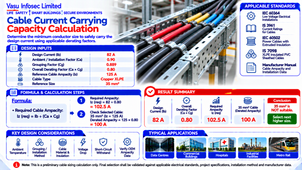
Required reference ampacity = 82 A ÷ 0.80 = 102.5 A. The selected cable must meet this requirement after applying the applicable installation correction factors; final selection requires manufacturer ampacity data.
At a Glance
| Item | Source value / outcome | ||
| Design Current | Ib | 82 | A |
| Ambient / Installation Factor | Ca | 0.90 | – |
| Grouping Factor | Cg | 0.889 | – |
| Overall Derating Factor | Ca × Cg | 0.80 | – |
| Reference Cable Ampacity | Iz | 125 | A |
| Cable Type | – | Copper XLPE | – |
| Reference Size | – | 35 | mm² |
Technical Calculation
1. Purpose
To determine the minimum conductor size required to safely carry the design current of an electrical circuit after applying appropriate installation and derating considerations.
2. Engineering Objective
To establish the minimum cable ampacity required from the design current and applicable correction factors, and to identify a suitable standard conductor size.
3. Applicable Standards
| Standard | Description |
| IEC 60364 | Low Voltage Electrical Installations |
| IS 3961 | Current Ratings for Cables |
| IEC 60502 | Power Cables with Extruded Insulation |
| IS 7098 | XLPE Insulated PVC Sheathed Cables where applicable |
| Manufacturer Manual | Cable ampacity, installation method and derating data |
4. Design Inputs
| Parameter | Symbol | Value | Unit |
| Design Current | Ib | 82 | A |
| Ambient / Installation Factor | Ca | 0.90 | – |
| Grouping Factor | Cg | 0.889 | – |
| Overall Derating Factor | Ca × Cg | 0.80 | – |
| Reference Cable Ampacity | Iz | 125 | A |
| Cable Type | – | Copper XLPE | – |
| Reference Size | – | 35 | mm² |
5. Assumptions
The design current is 82 A. The worked example assumes a copper XLPE insulated cable, ambient temperature and grouping conditions represented by an overall derating factor of 0.80. Final ampacity shall be verified from the selected cable manufacturer’s data and installation method.
6. Formula(s)
Required reference ampacity: Iz,required = Ib ÷ (Ca × Cg) = 82 ÷ 0.80 = 102.5 A. (Equation reconstructed from the stated design objective and inputs; confirm against the approved design method.)
7. Variables Explained
Ib = Design current (A), Ca = Ambient-temperature correction factor, Cg = Grouping correction factor, Iz = Corrected cable ampacity (A).
8. Step-by-Step Calculation
Area = 30 × 18 = 540 m²
Detector Quantity = 540 ÷ 81 = 6.67
Round Up = 7 Smoke Detectors.
9. Worked Engineering Example
For an 82 A design current and an overall derating factor of 0.80, the required reference ampacity is 102.5 A. A 35 mm² copper XLPE cable with a 125 A tabulated ampacity provides 100 A after derating and therefore does not satisfy the criterion; a larger standard conductor must be selected.
10. Engineering Output
Room Area: 540 m²
Coverage: 81 m² per detector
Calculated Quantity: 6.67
Required Quantity: 7 Nos.
11. Design Considerations
Verify cable ampacity using the applicable installation method, conductor material, insulation temperature rating, ambient temperature, grouping, soil conditions for buried cables, and manufacturer’s data.
12. Common Design Mistakes
Using free-air ampacity for a grouped installation, ignoring ambient temperature, using the conductor resistance or ampacity from an incorrect installation method, and failing to check voltage drop and short-circuit withstand.
13. Practical Site Notes
Coordinate cable selection with load schedules, voltage drop, protective-device rating, containment fill, termination ratings, earthing and short-circuit calculations.
14. Limitations
Preliminary cable sizing calculation only. Final selection shall be validated against applicable electrical standards, project specifications, installation method, OEM/manufacturer data and protection coordination.
15. Related Engineering Systems
LT Panels, MCCs, Transformers, DG Sets, UPS Systems, Protective Devices, Cable Trays, Earthing and Voltage Drop Design.
16. Cross References
Related FAQ: Fire Detection & Alarm Systems
Related White Paper: VEP-001
Related Case Study: CS-001
Related Diagram: ED-001
17. SEO Meta Title
Cable Current Carrying Capacity Calculation | EC-091
18. SEO Meta Description
Engineering calculation for cable current carrying capacity using design current and applicable installation derating factors.
19. URL Slug
ec-091-cable-current-carrying-capacity-calculation
20. Keywords (15)
Cable Ampacity, Current Carrying Capacity, Cable Sizing, IEC 60364, IS 3961, XLPE Cable, Copper Cable, Electrical Design, Derating Factor, Cable Selection, Power Distribution, Electrical Engineering, Voltage Drop, Engineering Calculation, Cable Protection
21. AI Search Summary
Cable current-carrying capacity must be corrected for installation conditions. For an 82 A design current with a 0.80 overall derating factor, at least 102.5 A reference ampacity is required; final cable selection must use applicable standard tables and manufacturer data.
Frequently Asked Questions
What is the purpose of this calculation?
To determine the minimum conductor size required to safely carry the design current of an electrical circuit after applying appropriate installation and derating considerations.
Which design inputs are used?
Design Current | Ib | 82 | A
Ambient / Installation Factor | Ca | 0.90 | –
Grouping Factor | Cg | 0.889 | –
Overall Derating Factor | Ca × Cg | 0.80 | –
Reference Cable Ampacity | Iz | 125 | A
Cable Type | – | Copper XLPE | –
Reference Size | – | 35 | mm²
SEO & Publishing Details
SEO title: Cable Current Carrying Capacity Calculation | EC-091
Meta description: Engineering calculation for cable current carrying capacity using design current and applicable installation derating factors.
URL slug: ec-091-cable-current-carrying-capacity-calculation
Keywords: Cable Ampacity, Current Carrying Capacity, Cable Sizing, IEC 60364, IS 3961, XLPE Cable, Copper Cable, Electrical Design, Derating Factor, Cable Selection, Power Distribution, Electrical Engineering, Voltage Drop, Engineering Calculation, Cable Protection
AI search summary: Cable current-carrying capacity must be corrected for installation conditions. For an 82 A design current with a 0.80 overall derating factor, at least 102.5 A reference ampacity is required; final cable selection must use applicable standard tables and manufacturer data.