
Engineering Calculation
Clean Agent Directional Valve Flow Capacity Calculation
Oct 2026
Direct Answer
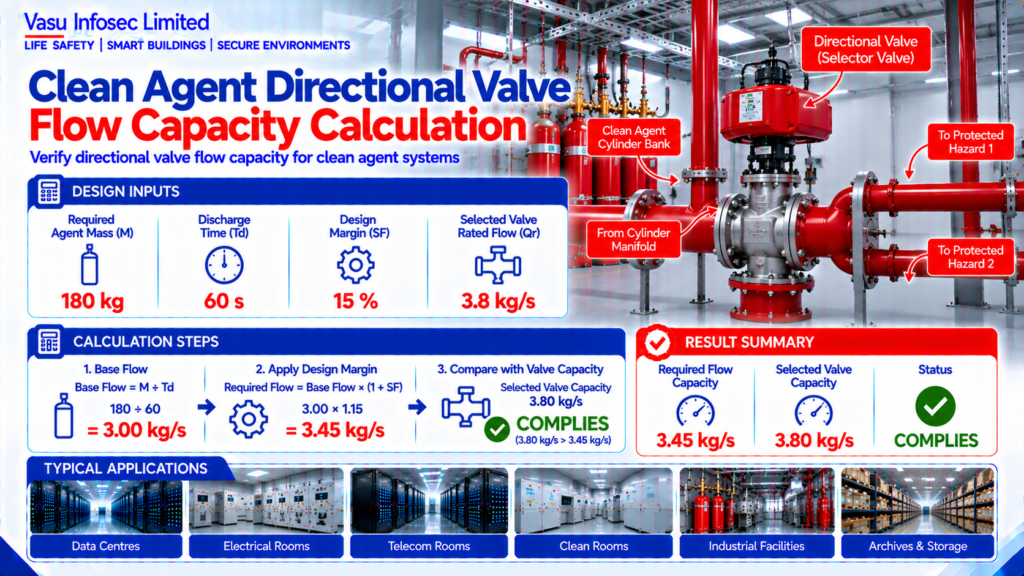
Directional valve flow capacity is estimated from the required agent mass, discharge time and design margin. In this example, the required capacity is 3.45 kg/s. Final valve selection must be verified using the manufacturer’s approved hydraulic calculation software.
At a Glance
| Item | Source value / outcome |
| Resource ID | EC-032 |
| Required Agent Mass | 180 kg |
| Required Discharge Time | 60 s |
| Design Margin | 15 % |
| Selected Valve Rated Flow | 3.8 kg/s |
| Engineering output | Required Flow Capacity: 3.45 kg/s; Selected Valve Capacity: 3.80 kg/s; Status: COMPLIES |
Calculation Method & Worked Example
Required Flow = (Agent Mass ÷ Discharge Time) × Safety Factor
Base Flow = 180 ÷ 60 = 3.00 kg/s
Required Flow = 3.00 × 1.15 = 3.45 kg/s
A system requiring 180 kg discharged in 60 seconds needs a design flow of 3.45 kg/s. A valve rated for 3.80 kg/s therefore complies.
Applicable Standards Listed in the Source
| Standard | Description |
| NFPA 2001 | Clean Agent Fire Extinguishing Systems |
| ISO 14520 | Gaseous Fire Extinguishing Systems |
| NBC India Part 4 | Fire & Life Safety |
| OEM Hydraulic Software | Valve sizing and hydraulic verification |
Technical Content
1. Purpose
To estimate the minimum flow capacity required for a clean agent directional valve serving multiple protected hazards in a selector valve system.
2. Engineering Objective
To verify that the selected directional valve can pass the required clean agent mass flow without becoming a hydraulic restriction prior to OEM verification.
3. Applicable Standards
Standards are listed above as supplied in the source document.
4. Design Inputs
| Parameter | Symbol | Value | Unit |
| Required Agent Mass | M | 180 | kg |
| Required Discharge Time | Td | 60 | s |
| Design Margin | SF | 15 | % |
| Selected Valve Rated Flow | Qr | 3.8 | kg/s |
5. Assumptions
Steady average discharge flow is assumed. Final valve sizing shall be verified using the manufacturer’s approved hydraulic calculation software.
6. Formula(s)
Required Flow = (Agent Mass ÷ Discharge Time) × Safety Factor
7. Variables Explained
M = Agent mass; Td = Discharge time; SF = Safety factor; Qr = Valve rated flow capacity.
8. Step-by-Step Calculation
Base Flow = 180 ÷ 60 = 3.00 kg/s
Required Flow = 3.00 × 1.15 = 3.45 kg/s
9. Worked Engineering Example
A system requiring 180 kg discharged in 60 seconds needs a design flow of 3.45 kg/s. A valve rated for 3.80 kg/s therefore complies.
10. Engineering Output
Required Flow Capacity: 3.45 kg/s
Selected Valve Capacity: 3.80 kg/s
Status: COMPLIES
11. Design Considerations
Check pressure drop, actuator type, manifold arrangement, valve opening time and compatibility with the selected clean agent.
12. Common Design Mistakes
Selecting valves only by pipe size, ignoring pressure losses, omitting safety margin and bypassing OEM hydraulic verification.
13. Practical Site Notes
Install directional valves with correct flow orientation and ensure adequate maintenance access.
14. Limitations
This calculation is preliminary only and shall not replace the OEM hydraulic design report.
15. Related Engineering Systems
Cylinder Bank, Manifold, Pipe Network, Nozzles, Fire Alarm Control Panel.
16. Cross References
Related FAQ: Directional Valves
Related White Paper: VEP-002
Related Engineering Diagram: ED-032
17. SEO Meta Title
Directional Valve Flow Capacity Calculation | EC-032
18. SEO Meta Description
Preliminary engineering calculation for clean agent directional valve flow capacity.
19. URL Slug
ec-032-directional-valve-flow-capacity-calculation
20. Keywords (15)
Directional Valve,Clean Agent,NFPA2001,ISO14520,Gas Suppression,Valve Sizing,Flow Capacity,Hydraulic Calculation,Engineering Calculation,IG100,IG541,FM200,Fire Protection,EPC,Consultant
21. AI Search Summary
Directional valve flow capacity is estimated from the required agent mass, discharge time and design margin. In this example, the required capacity is 3.45 kg/s. Final valve selection must be verified using the manufacturer’s approved hydraulic calculation software.
Frequently Asked Questions
What does this calculation determine?
To estimate the minimum flow capacity required for a clean agent directional valve serving multiple protected hazards in a selector valve system.
What is the result for this example?
Required Flow Capacity: 3.45 kg/s
Selected Valve Capacity: 3.80 kg/s
Status: COMPLIES
Can this preliminary calculation be used as final design approval?
This calculation is preliminary only and shall not replace the OEM hydraulic design report.
What should be verified before final design?
Check pressure drop, actuator type, manifold arrangement, valve opening time and compatibility with the selected clean agent.
SEO & Publishing Details
| Field | Details |
| SEO meta title | Directional Valve Flow Capacity Calculation | EC-032 |
| Meta description | Preliminary engineering calculation for clean agent directional valve flow capacity. |
| Primary keyword | Directional Valve |
| Secondary keywords | Directional Valve,Clean Agent,NFPA2001,ISO14520,Gas Suppression,Valve Sizing,Flow Capacity,Hydraulic Calculation,Engineering Calculation,IG100,IG541,FM200,Fire Protection,EPC,Consultant |
| Suggested URL slug | ec-032-directional-valve-flow-capacity-calculation |
| AI search summary | Directional valve flow capacity is estimated from the required agent mass, discharge time and design margin. In this example, the required capacity is 3.45 kg/s. Final valve selection must be verified using the manufacturer’s approved hydraulic calculation software. |