
Engineering Calculation
Clean Agent Pressure Switch Activation Verification Calculation
Oct 2026
Direct Answer
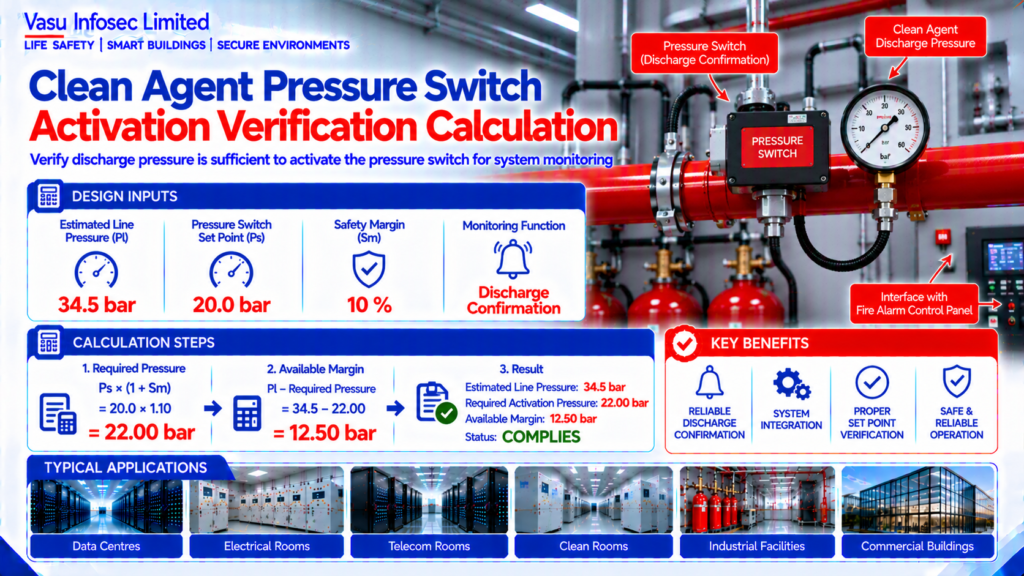
Pressure switch activation is verified by comparing estimated discharge pressure with the switch set point plus a safety margin. In this example, the available pressure is 34.5 bar and the system complies. Final verification should be completed through OEM calculations and commissioning tests.
At a Glance
| Item | Source value / outcome |
| Resource ID | EC-038 |
| Estimated Line Pressure | 34.5 bar |
| Pressure Switch Set Point | 20.0 bar |
| Safety Margin | 10 % |
| Monitoring Function | Discharge Confirmation – |
| Engineering output | Estimated Line Pressure: 34.5 bar; Required Activation Pressure: 22.00 bar; Status: COMPLIES |
Calculation Method & Worked Example
Required Pressure = Pressure Switch Set Point × (1 + Safety Margin)
Available Margin = Line Pressure − Required Pressure
Required Pressure = 20.0 × 1.10 = 22.00 bar
Available Margin = 34.5 − 22.00 = 12.50 bar
With an estimated discharge pressure of 34.5 bar and a pressure switch set point of 20.0 bar, the calculated operating margin is 12.50 bar.
Applicable Standards Listed in the Source
| Standard | Description |
| NFPA 2001 | Clean Agent Fire Extinguishing Systems |
| ISO 14520 | Gaseous Fire Extinguishing Systems |
| NFPA 72 | Fire Alarm and Signaling Code |
| OEM Installation Manual | Pressure switch settings and interface requirements |
Technical Content
1. Purpose
To verify that the clean agent discharge pressure is sufficient to activate the pressure switch used for system monitoring and interface functions.
2. Engineering Objective
To compare the estimated line pressure during discharge with the pressure switch activation set point and confirm adequate operating margin.
3. Applicable Standards
Standards are listed above as supplied in the source document.
4. Design Inputs
| Parameter | Symbol | Value | Unit |
| Estimated Line Pressure | Pl | 34.5 | bar |
| Pressure Switch Set Point | Ps | 20.0 | bar |
| Safety Margin | Sm | 10 | % |
| Monitoring Function | Discharge Confirmation | – |
5. Assumptions
Pressure is assumed at the pressure switch location during discharge. Final values shall be verified by OEM hydraulic calculations and commissioning tests.
6. Formula(s)
Required Pressure = Pressure Switch Set Point × (1 + Safety Margin)
Available Margin = Line Pressure − Required Pressure
7. Variables Explained
Pl = Estimated line pressure; Ps = Pressure switch set point; Sm = Safety margin.
8. Step-by-Step Calculation
Required Pressure = 20.0 × 1.10 = 22.00 bar
Available Margin = 34.5 − 22.00 = 12.50 bar
9. Worked Engineering Example
With an estimated discharge pressure of 34.5 bar and a pressure switch set point of 20.0 bar, the calculated operating margin is 12.50 bar.
10. Engineering Output
Estimated Line Pressure: 34.5 bar
Required Activation Pressure: 22.00 bar
Status: COMPLIES
11. Design Considerations
Verify switch location, response time, wiring supervision, interface logic and compatibility with the fire alarm control panel.
12. Common Design Mistakes
Installing the switch at an unsuitable location, ignoring pressure losses, incorrect set point selection and failing to functionally test the interface.
13. Practical Site Notes
Confirm pressure switch operation during integrated discharge or functional testing and record activation time.
14. Limitations
This is a preliminary engineering verification. Final acceptance shall be based on OEM hydraulic calculations and commissioning records.
15. Related Engineering Systems
Fire Alarm Control Panel, Gas Suppression Release Panel, Cylinder Manifold, Monitoring Interfaces.
16. Cross References
Related FAQ: Pressure Switches
Related White Paper: VEP-002
Related Engineering Diagram: ED-038
17. SEO Meta Title
Clean Agent Pressure Switch Verification | EC-038
18. SEO Meta Description
Engineering calculation for clean agent pressure switch activation verification.
19. URL Slug
ec-038-clean-agent-pressure-switch-activation-verification
20. Keywords (15)
Pressure Switch,Clean Agent,NFPA2001,NFPA72,ISO14520,Gas Suppression,Activation Pressure,Engineering Calculation,Fire Protection,Release Panel,IG100,IG541,FM200,EPC,Consultant
21. AI Search Summary
Pressure switch activation is verified by comparing estimated discharge pressure with the switch set point plus a safety margin. In this example, the available pressure is 34.5 bar and the system complies. Final verification should be completed through OEM calculations and commissioning tests.
Frequently Asked Questions
What does this calculation determine?
To verify that the clean agent discharge pressure is sufficient to activate the pressure switch used for system monitoring and interface functions.
What is the result for this example?
Estimated Line Pressure: 34.5 bar
Required Activation Pressure: 22.00 bar
Status: COMPLIES
Can this preliminary calculation be used as final design approval?
This is a preliminary engineering verification. Final acceptance shall be based on OEM hydraulic calculations and commissioning records.
What should be verified before final design?
Verify switch location, response time, wiring supervision, interface logic and compatibility with the fire alarm control panel.
SEO & Publishing Details
| Field | Details |
| SEO meta title | Clean Agent Pressure Switch Verification | EC-038 |
| Meta description | Engineering calculation for clean agent pressure switch activation verification. |
| Primary keyword | Pressure Switch |
| Secondary keywords | Pressure Switch,Clean Agent,NFPA2001,NFPA72,ISO14520,Gas Suppression,Activation Pressure,Engineering Calculation,Fire Protection,Release Panel,IG100,IG541,FM200,EPC,Consultant |
| Suggested URL slug | ec-038-clean-agent-pressure-switch-activation-verification |
| AI search summary | Pressure switch activation is verified by comparing estimated discharge pressure with the switch set point plus a safety margin. In this example, the available pressure is 34.5 bar and the system complies. Final verification should be completed through OEM calculations and commissioning tests. |