
Engineering Calculation
Data Centre Cooling Load Calculation
Nov 2026
Direct Answer
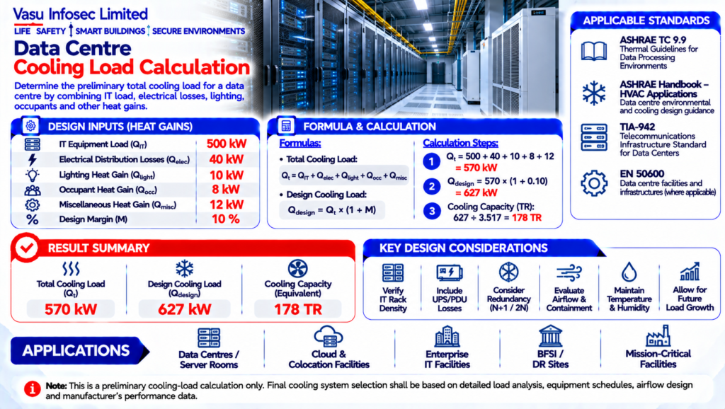
The source calculates a total cooling load of 570 kW and a design cooling load of 627 kW after a 10% margin (approximately 178 TR), subject to detailed thermal and equipment-performance verification.
At a Glance
| Item | Source value / outcome | ||
| IT Equipment Load | QIT | 500 | kW |
| Electrical Distribution Losses | Qelec | 40 | kW |
| Lighting Heat Gain | Qlight | 10 | kW |
| Occupant Heat Gain | Qocc | 8 | kW |
| Miscellaneous Heat Gain | Qmisc | 12 | kW |
| Design Margin | M | 10 | % |
| Total Cooling Load | Qt | 570 | kW |
| Design Cooling Load | Qdesign | 627 | kW |
Technical Calculation
1. Purpose
To determine the preliminary total cooling load for a data centre space by combining IT equipment load, electrical distribution losses, lighting, occupants and other heat gains.
2. Engineering Objective
To establish the sensible cooling capacity required for preliminary HVAC and cooling-system selection, with an allowance for design margin.
3. Applicable Standards
| Standard | Description |
| ASHRAE TC 9.9 | Thermal Guidelines for Data Processing Environments |
| ASHRAE Handbook – HVAC Applications | Data centre environmental and cooling design guidance |
| TIA-942 | Telecommunications Infrastructure Standard for Data Centers where applicable |
| EN 50600 | Data centre facilities and infrastructures where applicable |
| Manufacturer Data | IT equipment, CRAH/CRAC and cooling-system performance data |
4. Design Inputs
| Parameter | Symbol | Value | Unit |
| IT Equipment Load | QIT | 500 | kW |
| Electrical Distribution Losses | Qelec | 40 | kW |
| Lighting Heat Gain | Qlight | 10 | kW |
| Occupant Heat Gain | Qocc | 8 | kW |
| Miscellaneous Heat Gain | Qmisc | 12 | kW |
| Design Margin | M | 10 | % |
| Total Cooling Load | Qt | 570 | kW |
| Design Cooling Load | Qdesign | 627 | kW |
5. Assumptions
The worked example assumes a 500 kW IT load, 40 kW electrical distribution losses, 10 kW lighting load, 8 kW occupant load and 12 kW miscellaneous heat gain. A 10% design margin is applied. Final cooling capacity shall be verified against the approved IT load profile, equipment efficiency, environmental conditions and cooling-system design.
6. Formula(s)
Total load: Qt = QIT + Qelec + Qlight + Qocc + Qmisc = 500 + 40 + 10 + 8 + 12 = 570 kW; design load = Qt × 1.10 = 627 kW.
7. Variables Explained
QIT = IT heat load (kW), Qelec = electrical losses (kW), Qlight = lighting heat gain (kW), Qocc = occupant heat gain (kW), Qmisc = miscellaneous heat gain (kW), M = design margin, Qt = total cooling load (kW).
8. Step-by-Step Calculation
Area = 30 × 18 = 540 m²
Detector Quantity = 540 ÷ 81 = 6.67
Round Up = 7 Smoke Detectors.
9. Worked Engineering Example
A data centre with a 500 kW IT load and 70 kW of non-IT heat gains has a total preliminary cooling load of 570 kW. With a 10% design margin, the required cooling capacity is approximately 627 kW, equivalent to 178 TR.
10. Engineering Output
Room Area: 540 m²
Coverage: 81 m² per detector
Calculated Quantity: 6.67
Required Quantity: 7 Nos.
11. Design Considerations
Verify IT rack density, UPS losses, PDU losses, lighting, occupants, envelope gains, ventilation, humidity control and heat rejection requirements. Final selection should consider cooling redundancy and operating conditions.
12. Common Design Mistakes
Using only the IT electrical load, ignoring UPS/PDU losses, assuming all equipment efficiency is 100%, omitting future load growth, or selecting cooling equipment without checking sensible/latent performance and redundancy.
13. Practical Site Notes
Coordinate cooling load with CRAH/CRAC units, chilled-water or DX systems, containment, airflow management, UPS/PDU systems, generator systems, BMS/DCIM and emergency cooling operation.
14. Limitations
Preliminary cooling-load calculation only. Final data-centre thermal design shall be validated using detailed heat-load modelling, equipment schedules, airflow analysis and the selected cooling-system manufacturer’s performance data.
15. Related Engineering Systems
CRAH/CRAC Units, Chilled Water System, DX Cooling, Hot/Cold Aisle Containment, UPS, PDU, BMS/DCIM, Humidification and Generator Systems.
16. Cross References
Related FAQ: Fire Detection & Alarm Systems
Related White Paper: VEP-001
Related Case Study: CS-001
Related Diagram: ED-001
17. SEO Meta Title
Data Centre Cooling Load Calculation | EC-099
18. SEO Meta Description
Engineering calculation for preliminary data centre cooling load based on IT load, electrical losses, lighting, occupants, miscellaneous heat gains and design margin.
19. URL Slug
ec-099-data-centre-cooling-load-calculation
20. Keywords (15)
Data Centre Cooling Load, Data Centre HVAC, IT Heat Load, CRAH, CRAC, Cooling Capacity, Thermal Management, ASHRAE, Data Centre Design, UPS Losses, PDU Losses, Electrical Heat Gain, Engineering Calculation, Cooling System, Critical Facility
21. AI Search Summary
Data centre cooling load is determined by summing IT equipment heat, electrical losses, lighting, occupants and miscellaneous heat gains, then applying an appropriate design margin. For the worked example, 570 kW becomes 627 kW after a 10% margin, equivalent to approximately 178 TR.
Frequently Asked Questions
What is the purpose of this calculation?
To determine the preliminary total cooling load for a data centre space by combining IT equipment load, electrical distribution losses, lighting, occupants and other heat gains.
Which design inputs are used?
IT Equipment Load | QIT | 500 | kW
Electrical Distribution Losses | Qelec | 40 | kW
Lighting Heat Gain | Qlight | 10 | kW
Occupant Heat Gain | Qocc | 8 | kW
Miscellaneous Heat Gain | Qmisc | 12 | kW
Design Margin | M | 10 | %
Total Cooling Load | Qt | 570 | kW
Design Cooling Load | Qdesign | 627 | kW
SEO & Publishing Details
SEO title: Data Centre Cooling Load Calculation | EC-099
Meta description: Engineering calculation for preliminary data centre cooling load based on IT load, electrical losses, lighting, occupants, miscellaneous heat gains and design margin.
URL slug: ec-099-data-centre-cooling-load-calculation
Keywords: Data Centre Cooling Load, Data Centre HVAC, IT Heat Load, CRAH, CRAC, Cooling Capacity, Thermal Management, ASHRAE, Data Centre Design, UPS Losses, PDU Losses, Electrical Heat Gain, Engineering Calculation, Cooling System, Critical Facility
AI search summary: Data centre cooling load is determined by summing IT equipment heat, electrical losses, lighting, occupants and miscellaneous heat gains, then applying an appropriate design margin. For the worked example, 570 kW becomes 627 kW after a 10% margin, equivalent to approximately 178 TR.