
Engineering Calculation
Fire Alarm System Load Schedule Calculation
Oct 2026
Direct Answer
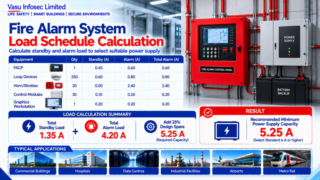
The source reports 1.35 A standby load and 4.20 A alarm load, producing a recommended minimum capacity of 5.25 A with a 25% factor; clarify current values against equipment quantities.
At a Glance
| Item | Source value / outcome | |||
| FACP | 1 | 0.45 | 0.60 | 0.60 |
| Loop Devices | 250 | 0.60 | 0.80 | 0.80 |
| Horn/Strobes | 20 | 0.00 | 2.40 | 2.40 |
| Control Modules | 30 | 0.10 | 0.20 | 0.20 |
| Graphics Workstation | 1 | 0.20 | 0.20 | 0.20 |
Technical Calculation
1. Purpose
To prepare and verify the total electrical load schedule for a fire alarm system by consolidating all connected equipment and confirming that the panel and power supplies are adequately sized.
2. Engineering Objective
To calculate the connected standby and alarm loads, verify spare capacity, and establish a documented load schedule for design, commissioning, and future expansion.
3. Applicable Standards
| Standard | Description |
| NFPA 72 | National Fire Alarm and Signaling Code |
| IS 2189 | Selection, Installation and Maintenance of Fire Detection and Alarm Systems |
| NBC India Part 4 | Fire & Life Safety |
| Manufacturer Manual | Equipment current ratings |
4. Design Inputs
| Equipment | Qty | Standby (A) | Alarm (A) | Total Alarm (A) |
| FACP | 1 | 0.45 | 0.60 | 0.60 |
| Loop Devices | 250 | 0.60 | 0.80 | 0.80 |
| Horn/Strobes | 20 | 0.00 | 2.40 | 2.40 |
| Control Modules | 30 | 0.10 | 0.20 | 0.20 |
| Graphics Workstation | 1 | 0.20 | 0.20 | 0.20 |
5. Assumptions
All alarm loads operate simultaneously during the worst-case fire condition. A 25% engineering spare factor is included.
6. Formula(s)
Total Standby Load = Σ Standby Currents
Total Alarm Load = Σ Alarm Currents
Required Capacity = Total Alarm Load × 1.25
7. Variables Explained
Σ = Sum of connected loads; Standby Load = Normal operating current; Alarm Load = Fire condition current.
8. Step-by-Step Calculation
Standby Load = 1.35 A
Alarm Load = 4.20 A
Required Capacity = 4.20 × 1.25 = 5.25 A
9. Worked Engineering Example
The calculated standby load is 1.35 A and the total alarm load is 4.20 A. After applying a 25% spare factor, the recommended minimum power capacity is 5.25 A.
10. Engineering Output
Standby Load: 1.35 A
Alarm Load: 4.20 A
Recommended Capacity: 5.25 A
11. Design Considerations
Verify equipment current ratings, battery sizing, voltage drop, auxiliary loads and future expansion allowances.
12. Common Design Mistakes
Omitting auxiliary equipment, using incorrect current ratings, excluding spare capacity and failing to update the load schedule after design revisions.
13. Practical Site Notes
Maintain the load schedule as a controlled engineering document and verify currents during commissioning.
14. Limitations
Final values shall be based on approved OEM data sheets and project-specific equipment selections.
15. Related Engineering Systems
Fire Alarm Control Panel, Battery Backup, NAC Circuits, Auxiliary Power Supplies, BMS.
16. Cross References
Related FAQ: Fire Alarm Power Supply
Related White Paper: VEP-001
Related Engineering Diagram: ED-020
17. SEO Meta Title
Fire Alarm System Load Schedule Calculation | EC-020
18. SEO Meta Description
Engineering calculation for fire alarm system load schedule with standby and alarm current assessment.
19. URL Slug
ec-020-fire-alarm-system-load-schedule-calculation
20. Keywords (15)
Fire Alarm Load Schedule, Standby Load, Alarm Load, NFPA72, IS2189, Fire Alarm Engineering, Current Calculation, FACP, Battery Sizing, Power Supply, Engineering Calculation, EPC, Consultant, Life Safety, Electrical Load
21. AI Search Summary
A fire alarm load schedule is prepared by summing all standby and alarm currents and applying an engineering spare factor. In this example, the alarm load is 4.20 A and the recommended minimum capacity is 5.25 A.
Frequently Asked Questions
What loads are reported?
The source reports 1.35 A standby and 4.20 A alarm load.
What should be confirmed?
Clarify whether listed currents are category totals or per-unit values and use approved OEM data sheets.
SEO & Publishing Details
SEO title: Fire Alarm System Load Schedule Calculation | EC-020
Meta description: Engineering calculation for fire alarm system load schedule with standby and alarm current assessment.
URL slug: ec-020-fire-alarm-system-load-schedule-calculation
Keywords: Fire Alarm Load Schedule, Standby Load, Alarm Load, NFPA72, IS2189, Fire Alarm Engineering, Current Calculation, FACP, Battery Sizing, Power Supply, Engineering Calculation, EPC, Consultant, Life Safety, Electrical Load
AI search summary: A fire alarm load schedule is prepared by summing all standby and alarm currents and applying an engineering spare factor. In this example, the alarm load is 4.20 A and the recommended minimum capacity is 5.25 A.