
Engineering Calculation
Sprinkler Design Density Calculation
Nov 2026
Direct Answer
Sprinkler water demand is calculated by multiplying the hydraulic design area by the selected design density. In this example, the preliminary demand is 1879.20 L/min and the recommended design flow is 2067.12 L/min. Final hydraulic verification should be completed using approved sprinkler calculation software.
At a Glance
| Item | Source value / outcome |
| Resource ID | EC-056 |
| Calculation / subject | Sprinkler Design Density Calculation |
| Hydraulic Design Area | A | 232 | m² |
| Design Density | D | 8.1 | L/min/m² |
| Safety Margin | SF | 10 | % |
| Hazard Classification | | Ordinary Hazard Group 2 | – |
Calculation Method & Worked Example
Required Flow = Design Area × Design Density
Recommended Flow = Required Flow × (1 + Safety Margin)
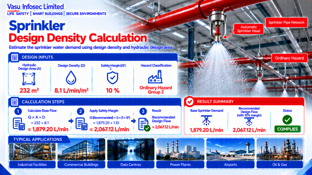
Base Flow = 232 × 8.1 = 1879.20 L/min
Recommended Flow = 1879.20 × 1.10 = 2067.12 L/min
For an Ordinary Hazard Group 2 area of 232 m² protected at 8.1 L/min/m², the calculated sprinkler demand is 1879.20 L/min. Including a 10% engineering margin, the recommended design flow is 2067.12 L/min.
Base Sprinkler Demand: 1879.20 L/min
Recommended Design Flow: 2067.12 L/min
Applicable Standards Listed in the Source
| Standard | Description |
| NFPA 13 | Standard for the Installation of Sprinkler Systems |
| NBC India Part 4 | Fire & Life Safety |
| IS 15105 | Automatic Sprinkler Systems |
| Hydraulic Calculation Software | Final sprinkler hydraulic verification |
Technical Content
- Purpose
To estimate the preliminary sprinkler system water demand using the selected design density and hydraulically remote design area.
- Engineering Objective
To determine the required sprinkler discharge flow for conceptual hydraulic design. Final calculations shall be verified using approved hydraulic calculation software and the selected sprinkler manufacturer’s data.
- Applicable Standards
- Design Inputs
| Parameter | Symbol | Value / Unit |
| Hydraulic Design Area | A | 232 m² |
| Design Density | D | 8.1 L/min/m² |
| Safety Margin | SF | 10 % |
| Hazard Classification | Ordinary Hazard Group 2 – |
- Assumptions
The hydraulically remote design area operates simultaneously. A 10% engineering margin is included for preliminary sizing.
- Formula(s)
Required Flow = Design Area × Design Density
Recommended Flow = Required Flow × (1 + Safety Margin)
- Variables Explained
A = Hydraulic design area (m²); D = Design density (L/min/m²); SF = Safety margin.
- Step-by-Step Calculation
Base Flow = 232 × 8.1 = 1879.20 L/min
Recommended Flow = 1879.20 × 1.10 = 2067.12 L/min
- Worked Engineering Example
For an Ordinary Hazard Group 2 area of 232 m² protected at 8.1 L/min/m², the calculated sprinkler demand is 1879.20 L/min. Including a 10% engineering margin, the recommended design flow is 2067.12 L/min.
- Engineering Output
Base Sprinkler Demand: 1879.20 L/min
Recommended Design Flow: 2067.12 L/min
- Design Considerations
Confirm hazard classification, design area, hose stream allowance where applicable, K-factor selection, pressure requirements and hydraulic remote area.
- Common Design Mistakes
Using the wrong hazard classification, omitting safety margin, ignoring hydraulic remote area and relying on manual calculations for final approval.
- Practical Site Notes
Coordinate sprinkler layout with HVAC, lighting and structural elements before detailed hydraulic calculations.
- Limitations
This is a preliminary engineering calculation only. Final hydraulic design shall be verified using approved sprinkler hydraulic calculation software.
- Related Engineering Systems
Fire Water Tank, Fire Pump, Sprinkler Network, Alarm Valve, Hydrant System.
- Cross References
Related FAQ: Sprinkler Hydraulic Design
Related White Paper: VEP-004
Related Engineering Diagram: ED-056
- SEO Meta Title
Sprinkler Design Density Calculation | EC-056
- SEO Meta Description
Engineering calculation for preliminary sprinkler design density and water demand.
- URL Slug
ec-056-sprinkler-design-density-calculation
- Keywords (15)
Sprinkler,NFPA13,IS15105,Design Density,Hydraulic Calculation,Ordinary Hazard,Sprinkler Flow,Engineering Calculation,Fire Protection,Fire Pump,EPC,Consultant,Hydraulic Design,Life Safety,Water Demand
- AI Search Summary
Sprinkler water demand is calculated by multiplying the hydraulic design area by the selected design density. In this example, the preliminary demand is 1879.20 L/min and the recommended design flow is 2067.12 L/min. Final hydraulic verification should be completed using approved sprinkler calculation software.
Frequently Asked Questions
What does sprinkler design density calculation determine?
To estimate the preliminary sprinkler system water demand using the selected design density and hydraulically remote design area.
Can this preliminary calculation be used as final design approval?
No. This is a preliminary engineering calculation only. Final hydraulic design shall be verified using approved sprinkler hydraulic calculation software.
What must be confirmed before final design?
Confirm project inputs, design criteria, equipment data, applicable approvals and the approved manufacturer’s or hydraulic calculation method.
SEO & Publishing Details
SEO Meta Title: Sprinkler Design Density Calculation | EC-056
SEO Meta Description: Engineering calculation for preliminary sprinkler design density and water demand.
URL Slug: ec-056-sprinkler-design-density-calculation
Keywords (15): Sprinkler,NFPA13,IS15105,Design Density,Hydraulic Calculation,Ordinary Hazard,Sprinkler Flow,Engineering Calculation,Fire Protection,Fire Pump,EPC,Consultant,Hydraulic Design,Life Safety,Water Demand
AI Search Summary: Sprinkler water demand is calculated by multiplying the hydraulic design area by the selected design density. In this example, the preliminary demand is 1879.20 L/min and the recommended design flow is 2067.12 L/min. Final hydraulic verification should be completed using approved sprinkler calculation software.