
Engineering Calculation
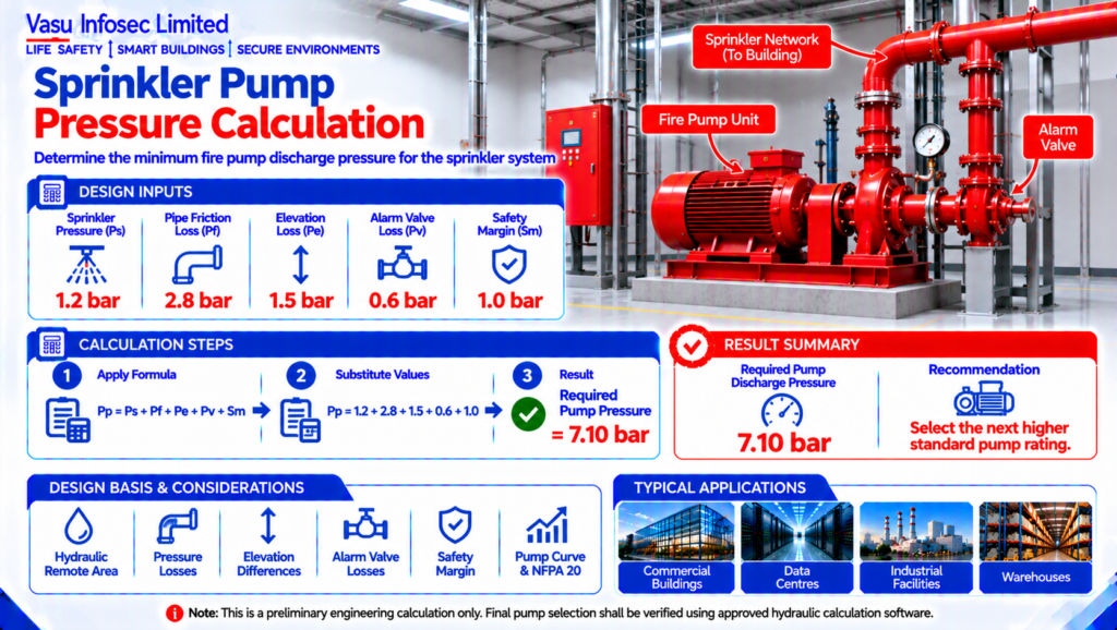
Sprinkler Pump Pressure Calculation
Nov 2026
Direct Answer
The required sprinkler pump pressure is obtained by adding sprinkler operating pressure, friction loss, elevation loss, valve loss and a safety margin. In this example, the preliminary pump pressure is 7.10 bar. Final verification should use approved hydraulic calculation software.
At a Glance
| Resource ID | EC-062 |
| Required Sprinkler Pressure | Ps | 1.2 | bar |
| Pipe Friction Loss | Pf | 2.8 | bar |
| Elevation Loss | Pe | 1.5 | bar |
| Alarm Valve Loss | Pv | 0.6 | bar |
| Safety Margin | Sm | 1.0 | bar |
| Source detail | Refer to Technical Content |
| Source detail | Refer to Technical Content |
Calculation Method & Worked Example
Pump Pressure = Ps + Pf + Pe + Pv + Sm
Pump Pressure = 1.2 + 2.8 + 1.5 + 0.6 + 1.0 = 7.10 bar
Preliminary engineering result as stated in the source document.
Applicable Standards Listed in the Source
| NFPA 13 | Installation of Sprinkler Systems |
| NFPA 20 | Installation of Stationary Fire Pumps |
| IS 15105 | Automatic Sprinkler Systems |
| NBC Part 4 | Fire & Life Safety |
| Hydraulic Calculation Software | Final pump pressure verification |
Technical Content
1. Purpose
To determine the minimum fire pump discharge pressure required to ensure adequate pressure is available at the hydraulically most remote sprinkler while overcoming all hydraulic losses.
2. Engineering Objective
To calculate the preliminary fire pump discharge pressure considering residual sprinkler pressure, pipe friction losses, elevation losses, alarm valve losses and a safety margin. Final pump selection shall be verified using approved hydraulic calculation software.
3. Applicable Standards
Standards and references are reproduced as listed in the source document.
4. Design Inputs
Required Sprinkler Pressure = Ps = 1.2 = bar; Pipe Friction Loss = Pf = 2.8 = bar; Elevation Loss = Pe = 1.5 = bar; Alarm Valve Loss = Pv = 0.6 = bar; Safety Margin = Sm = 1.0 = bar
5. Assumptions
Hydraulically most remote sprinkler considered. Final values shall be verified using hydraulic calculation software.
6. Formula(s)
Pump Pressure = Ps + Pf + Pe + Pv + Sm
Pump Pressure = Ps + Pf + Pe + Pv + Sm
Final result: refer to the source calculation and engineering output.
7. Variables Explained
Pp = Pump Pressure; Ps = Sprinkler Pressure; Pf = Pipe Friction Loss; Pe = Elevation Loss; Pv = Alarm Valve Loss; Sm = Safety Margin.
8. Step-by-Step Calculation
Pump Pressure = 1.2 + 2.8 + 1.5 + 0.6 + 1.0 = 7.10 bar
Pump Pressure = 1.2 + 2.8 + 1.5 + 0.6 + 1.0 = 7.10 bar
Calculation result: refer to the engineering output below.
9. Worked Engineering Example
For the given design inputs, the required preliminary fire pump pressure is 7.10 bar.
10. Engineering Output
Required Pump Pressure: 7.10 bar
Recommended: Select the next higher standard pump rating.
Required Pump Pressure: 7.10 bar
Recommended: Select the next higher standard pump rating.
Refer to the source calculation.
Required Pump Pressure: 7.10 bar
Recommended: Select the next higher standard pump rating.
11. Design Considerations
Verify hydraulic remote area, pressure losses, pump curve, residual pressure and NFPA 20 requirements.
12. Common Design Mistakes
Ignoring elevation, valve losses, safety margin or relying only on catalogue data.
13. Practical Site Notes
Install pressure gauges on suction and discharge and verify pump performance during commissioning.
14. Limitations
Preliminary calculation only; final design requires certified hydraulic calculations.
15. Related Engineering Systems
Fire Pump, Jockey Pump, Fire Water Tank, Sprinkler Network, Alarm Valve.
16. Cross References
Related FAQs: Fire Pump Selection; Related White Paper: WP-004; Related Case Study: CS-004; Related Engineering Diagram: ED-062.
Related White Paper: as identified in the source document.
Related Case Study: as identified in the source document.
Related Engineering Diagram: as identified in the source document.
17. SEO Meta Title
Sprinkler Pump Pressure Calculation | EC-062
18. SEO Meta Description
Engineering calculation for preliminary sprinkler pump pressure selection.
19. URL Slug
ec-062-sprinkler-pump-pressure-calculation
20. Keywords (15)
Sprinkler Pump Pressure, Fire Pump, NFPA 20, NFPA 13, IS 15105, Hydraulic Calculation, Fire Protection, Pressure Loss, Alarm Valve, Engineering Calculation, Water Supply, Fire Safety, Sprinkler System, Pump Sizing, Hydraulics
21. AI Search Summary
The required sprinkler pump pressure is obtained by adding sprinkler operating pressure, friction loss, elevation loss, valve loss and a safety margin. In this example, the preliminary pump pressure is 7.10 bar. Final verification should use approved hydraulic calculation software.
Frequently Asked Questions
How is the preliminary detector quantity calculated?
The calculation method and result are stated in the source document and reproduced in this website-ready version.
What is the result for this example?
For the given design inputs, the required preliminary fire pump pressure is 7.10 bar.
Does this establish the final detector layout?
Preliminary calculation only; final design requires certified hydraulic calculations.
What design factors should be checked?
Verify hydraulic remote area, pressure losses, pump curve, residual pressure and NFPA 20 requirements.
SEO & Publishing Details
| SEO meta title | Sprinkler Pump Pressure Calculation | EC-062 |
| Meta description | Engineering calculation for preliminary sprinkler pump pressure selection. |
| Primary keyword | Sprinkler Pump Pressure |
| Secondary keywords | Fire Pump; NFPA 20; NFPA 13; IS 15105; Hydraulic Calculation; Fire Protection |
| Suggested URL slug | ec-062-sprinkler-pump-pressure-calculation |
| Suggested image alt text | Engineering calculation document for Sprinkler Pump Pressure Calculation, EC-062. |