
Engineering Calculation
Structured Cabling Backbone Fiber Core Calculation
Nov 2026
Direct Answer
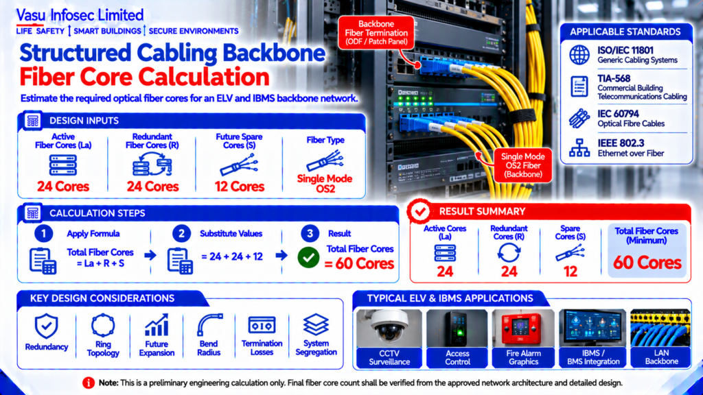
Backbone fiber core requirements are estimated by adding active, redundant and spare optical fibers. In this example, the calculated requirement is 60 cores. Final fiber sizing should be verified against the approved network architecture and project-specific design.
At a Glance
| Resource ID | EC-067 |
| Active Fiber Cores | La | 24 | Cores |
| Redundant Fiber Cores | R | 24 | Cores |
| Future Spare Cores | S | 12 | Cores |
| Fiber Type | Single Mode OS2 | – |
| Source detail | Refer to Technical Content |
| Source detail | Refer to Technical Content |
| Source detail | Refer to Technical Content |
Calculation Method & Worked Example
Total Fiber Cores = Active Cores + Redundant Cores + Spare Cores
Total Fiber Cores = 24 + 24 + 12 = 60 cores
Preliminary engineering result as stated in the source document.
Applicable Standards Listed in the Source
| ISO/IEC 11801 | Generic Cabling Systems |
| TIA-568 | Commercial Building Telecommunications Cabling |
| IEC 60794 | Optical Fibre Cables |
| IEEE 802.3 | Ethernet over Fiber |
Technical Content
1. Purpose
To estimate the minimum number of optical fiber cores required for a structured cabling backbone serving an ELV and IBMS network.
2. Engineering Objective
To determine the preliminary backbone fiber core count by considering active links, redundancy and future expansion. Final fiber sizing shall be verified during detailed network design.
3. Applicable Standards
Standards and references are reproduced as listed in the source document.
4. Design Inputs
Active Fiber Cores = La = 24 = Cores; Redundant Fiber Cores = R = 24 = Cores; Future Spare Cores = S = 12 = Cores; Fiber Type = Single Mode OS2 = –
5. Assumptions
One working and one redundant backbone path are considered. Spare fibers are included for future expansion and maintenance.
6. Formula(s)
Total Fiber Cores = Active Cores + Redundant Cores + Spare Cores
Total Fiber Cores = Active Cores + Redundant Cores + Spare Cores
Final result: refer to the source calculation and engineering output.
7. Variables Explained
La = Active cores; R = Redundant cores; S = Spare cores.
8. Step-by-Step Calculation
Total Fiber Cores = 24 + 24 + 12 = 60 cores
Total Fiber Cores = 24 + 24 + 12 = 60 cores
Calculation result: refer to the engineering output below.
9. Worked Engineering Example
A backbone requiring 24 active cores, 24 redundant cores and 12 spare cores requires a minimum of 60 optical fiber cores.
10. Engineering Output
Calculated Minimum Fiber Cores: 60
Recommended Standard Cable: 60-core or next higher standard size, subject to project requirements.
Calculated Minimum Fiber Cores: 60
Recommended Standard Cable: 60-core or next higher standard size, subject to project requirements.
Refer to the source calculation.
Calculated Minimum Fiber Cores: 60
Recommended Standard Cable: 60-core or next higher standard size, subject to project requirements.
11. Design Considerations
Consider redundancy, ring topology, future expansion, segregation, bend radius and termination losses.
12. Common Design Mistakes
No spare cores, inadequate redundancy, mixing multimode and single-mode requirements, underestimating future growth.
13. Practical Site Notes
Use labeled fiber trays, maintain bend radius, and provide spare termination capacity in ODF panels.
14. Limitations
This is a preliminary engineering calculation. Final core count shall be verified from the approved network architecture and detailed design.
15. Related Engineering Systems
IBMS, CCTV, Access Control, Fire Alarm Graphics, LAN Backbone.
16. Cross References
Related FAQ: Fiber Backbone Design
Related White Paper: WP-005
Related Case Study: CS-005
Related Engineering Diagram: ED-067
Related White Paper: as identified in the source document.
Related Case Study: as identified in the source document.
Related Engineering Diagram: as identified in the source document.
17. SEO Meta Title
Structured Cabling Backbone Fiber Core Calculation | EC-067
18. SEO Meta Description
Engineering calculation for preliminary backbone fiber core sizing for ELV and IBMS systems.
19. URL Slug
ec-067-structured-cabling-backbone-fiber-core-calculation
20. Keywords (15)
Fiber Core Calculation,Structured Cabling,OS2 Fiber,TIA568,ISO11801,Backbone Fiber,ELV,IBMS,Engineering Calculation,Optical Fiber,LAN Backbone,CCTV,Access Control,Fire Alarm,Fiber Design
21. AI Search Summary
Backbone fiber core requirements are estimated by adding active, redundant and spare optical fibers. In this example, the calculated requirement is 60 cores. Final fiber sizing should be verified against the approved network architecture and project-specific design.
Frequently Asked Questions
How is the preliminary detector quantity calculated?
The calculation method and result are stated in the source document and reproduced in this website-ready version.
What is the result for this example?
A backbone requiring 24 active cores, 24 redundant cores and 12 spare cores requires a minimum of 60 optical fiber cores.
Does this establish the final detector layout?
This is a preliminary engineering calculation. Final core count shall be verified from the approved network architecture and detailed design.
What design factors should be checked?
Consider redundancy, ring topology, future expansion, segregation, bend radius and termination losses.
SEO & Publishing Details
| SEO meta title | Structured Cabling Backbone Fiber Core Calculation | EC-067 |
| Meta description | Engineering calculation for preliminary backbone fiber core sizing for ELV and IBMS systems. |
| Primary keyword | Fiber Core Calculation |
| Secondary keywords | Structured Cabling; OS2 Fiber; TIA568; ISO11801; Backbone Fiber; ELV |
| Suggested URL slug | ec-067-structured-cabling-backbone-fiber-core-calculation |
| Suggested image alt text | Engineering calculation document for Structured Cabling Backbone Fiber Core Calculation, EC-067. |